
User's Manual
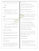


1 Insert one of the wires required for your device
into the appropriate opening in the Pluggable
Terminal Block you reserved for that device (refer
to Figure 1 below). For example, if you add a
motion sensor, you would connect its wires to the
following Contact openings: power input to +12V
output signal to SIG, and ground connector to
GND. See the following sections for instructions
about connecting the various protocols.
2 Repeat Step 1 for all wires required for your
device.
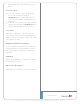
Note: When you connect dry contact closure
devices, such as door switches, connect the
switch between +12V (Power) and SIG (Signal).
Connect to the Contact Port
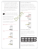
The HC-800 provides four (4) contact ports for the
pluggable terminal block provided.
See the following figures to determine how to
connect the device to a contact port.
Figure 3. Contact Port for Voltage Source (e.g.,
Motion Sensor)
Figure 4. Contact for Dry Contact (e.g., Door Contact
Sensor)
Figure 5. Contact for Self-Powered Voltage Source
Device
Connect to the Relay Port
The HC-800 provides four (4) relay ports for
the pluggable terminal block provided. For most
applications, attach one (1) wire to the common
terminal and the other to the normally open terminal.
The relay switches close when the relay is activated.
The HC-800 can support applications that require a
normally closed contact.
Figure 6. Relay Port: Normally Open
Figure 7. Relay Port: Normally Closed
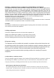
Connect the Serial Ports
The HC-800 has two (2) DB9-style serial ports.
Connect a device, for example, a receiver or disc
changer to the HC-800 by aligning the pins and
tightening the screws.
See the next table for serial communication values.
Hardware
Flow
Control
Odd
Parity
Even
Parity
No Parity
Serial Port 1 X X X
Serial Port 2 X X X X
Set Up IR Emitters or IR Blaster
Your system may contain third-party products
that are controlled with IR commands (usually
through remote controls). To provide a way for the
Draft