Disclaimer Control4® makes no representations or warranties with respect to the contents or use of this manual, and specifically disclaims any express or implied warranties of merchantability or fitness for any particular purpose. Control4 reserves the right to revise this publication and to make changes to its content, at any time, without obligation to notify any person or entity of such revisions or changes.
Contents Preface About This Guide........................................... 1 Notes, Tips, Cautions, and Warnings .... 1 Additional Resources ............................. 2 Chapter 1 Introduction to Audio Matrix Switch ............... 3 Features and Benefits............................ 3 Home Network Requirements................ 4 What’s in the Box ................................... 4 About the Audio Matrix Switch ............... 4 Front View with Door Opened........... 4 Back View ...................
Warranty .............................................. 21 Limited Hardware Warranty ............ 21 Hardware Warranty Terms ............. 22 Software Agreement ....................... 25 Regulatory Compliance ....................... 26 FCC Interference Statement........... 26 FCC Caution ................................... 27 Canadian EMC Statement .............. 27 UL ...................................................
PREFACE About This Guide Notes, Tips, Cautions, and Warnings Audio Matrix Switch Installation and User Guide Note, Tip, Caution, and Warning paragraphs draw your attention to safe practices and additional information which may help you avoid losing data or time. NOTE: These contain notes on related information about the current topic. TIP: These provide tips that may save you time or effort.
Additional Resources The following resources are available to provide you with additional support. 2 ` Your authorized Control4 representative or reseller. ` Control4 Web Site: http://www.Control4.
CHAPTER 1 Introduction to Audio Matrix Switch Control4 systems are uniquely configured for every customer and every site. A popular component among music lovers is the Control4 Audio Matrix Switch. This chapter introduces the Control4 Audio Matrix Switch and its features. Features and Benefits ` Switches up to 16 input sources to up to 16 simultaneous output zones. ` Front display for adjustments to zone settings and routing sources.
Home Network Requirements In order for Audio Matrix Switch to be managed and controlled from the Control4 user interfaces, it must communicate with the system through either a wired (Ethernet) or wireless (ZigBee) network. If you want to use an Ethernet connection for Audio Matrix Switch, ensure that your home network wiring is in place before starting your system setup. What’s in the Box The following items are included in your Control4 Audio Matrix Switch box.
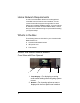
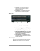
3. Select Dial—For scrolling through and selecting screen elements or options displayed in the LCD. 4. Reset Button—For troubleshooting option behind the door to refresh the system. Back View 2 1 3 4 1. Ethernet—RJ-45 for a 10/100 Mb Ethernet connection. 2. Audio In (Left-Right pairs) 1-16—RCA jacks and supporting LED for stereo channel input for up to 16 stereo analog sources. 3. Audio Out (Left-Right pairs) 1-16—RCA jacks and supporting LED for stereo channel line output for up to 16 amplifiers. 4.
Audio Outputs The system automatically creates generic source names that are displayed in the front display. To change these names, you must update your system using the supported system designing software (such as Composer Pro on a PC). For more information, refer to the documentation that shipped with your Control4 controller or contact your professional installer or reseller.
Technical Specifications Table 1-1.
Table 1-1. Audio Matrix Switch Technical Specifications Any In to Any Out ? Hz to ? kHz, +0/-3 dB Any In to All Outs ? Hz to ? kHz, +0/-3 dB Signal-to-Noise Ratio: Any In to Any Out ? dB typical, 22 Hz to 22 kHz, unweighted ? dB typical, 22 Hz to 22 kHz, A-weighted Dynamic Range: Any In to Any Out ? dB typical, 22 Hz to 22 kHz, unweighted ? dB typical, 22 Hz to 22 kHz, A-weighted THD+Noise: Any In to Any Out Typically < 0.0x% at 1 kHz, -10 dBV, unity gain Typically < 0.
CHAPTER 2 Set Up Audio Matrix Switch This device operates as part of the Control4 home system, which requires physical and logical connections to function as designed. The essential setup tasks are: 1.Plan Your Physical Layout 2.Connect Input and Output Devices 3.Connect to the Network and Power 4.Set Up Logical Connections This chapter describes, in general terms, how to set up the physical connections required for the Audio Matrix Switch and all of the devices associated with it.
Table 2-1. Audio Matrix Switch Routing Worksheet RCA Pair # 1. 2. 3. 4. 5. 6. 7. 8. 9. 10. 11. 12. 13. 14. 15. 16. 10 Audio In Sources—RCA (Left-Right) pairs for stereo channel input for up to 16 stereo analog sources. Audio Out Zones—RCA (Left-Right) pairs for stereo channel output for up to 16 output zones.
Connect Input and Output Devices 1. Connect the audio source devices (such as CD changers or players, DVD changers or players, or tape players) you want included in the system to the Audio In jacks. 2. Connect amplifiers or amplified speakers as needed to the Audio Out jacks. NOTE: If you are not sure which jacks to use, try using the worksheet provided in Table 2-1 to plan your routes. Connect to the Network and Power 1.
12
CHAPTER 3 Use Audio Matrix Switch This chapter introduces the user interface available to Audio Matrix Switch users and the common system tasks you can perform with Audio Matrix Switch from the front display. NOTE: Following the initial setup, you may never need to overtly communicate with the Audio Matrix Switch again. This device simply assists in fulfilling a roomspecific music request.
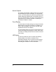
Output to Input 1- 1 5- 9- 13- 2- 6-3 10- 14- 3-4 7- 11- 15- 4- 8- 12- 16- OUT/IN NETWORK DISPLAY Manage Outputs Change Output Assignments To change up your “Output to Input” assignments: 1. Ensure your Audio Matrix Switch is powered up and that the Output to Input screen is displaying in the front display. 2. On the Output to Input screen, view the current output-to-input associations.
Output to Input OUT/IN NETWORK DISPLAY The screen consists of 16 output zones and any assigned input source. When an input source is highlighted (as Input 1 in this example), the highlighting indicates that a signal is present. The buttons on the front panel provide access to these menu options: ` Out/In: Displays an Output-specific screen. The most recent screen accessed is displayed by default, but you can choose to view a different output’s setting by changing the Output number.
From the output screen, you can: (1) change to another output screen; (2) change the output settings on the screen; or (3) toggle to the Input Signal Sensing screen. 1a. If the Output-specific screen that you want to view did not display (such as Output 3 in the previous example), use the Select Dial to highlight and select the Output number and then change it. 1b.
5. Press the Inputs button to go to the Input Signal Sensing screen, OR press the Exit button to return to the Output to Input screen. Check Signal Status 1. From the Output to Input screen, press the Out/In button, then press the Inputs button to access the Input Signal Sensing screen. Input Signal Sensing 1 5o _9 o 13 o 2o 6o 10 o 14 o 3o 7o 11 o 15 o 4o 8o 12 o 16 o OUTPUTS EXIT 2.
Network - Ethernet DHCP enabled IP 255.255.255.255 Mask 0.0.0.0 GWay 0.0.0.0 EXIT Set Front Display Preferences To set your viewing preferences for the front display: 1. On the Output to Input screen, press the Display button. The Display Configuration screen displays.
2. Use the buttons and/or the Select Dial to choose a setting to change: Once you press the Select button (or press the dial), you enter Edit mode. Display Configuration Brightness: Contrast: 100 100 Backlight Time: 10 DOWN UP SELECT EXIT 3. In Edit mode, use the buttons or Select Dial to change the highlighted setting; then press the OK button (or press the dial) to save the change and exit Edit mode.
20
CHAPTER 4 Warranty and Regulatory Compliance Warranty Important: Warranty terms may be different with the country of purchase; contact your Authorized Control4 Sales and Service office for detailed product warranty information. Limited Hardware Warranty Control4 warrants its Audio Matrix Switch product to be free from defects in material and workmanship during the warranty period.
Hardware Warranty Terms READ THESE WARRANTY TERMS CAREFULLY BEFORE INSTALLING OR USING THE CONTROL4 SYSTEM OR COMPONENTS. YOUR INSTALLATION AND USE OF THE SYSTEM OR ANY OF ITS COMPONENTS INDICATES THAT YOU AGREE TO BE BOUND BY THESE TERMS. IF YOU DO NOT AGREE TO ALL OF THE TERMS OF THIS WARRANTY, RETURN THE PRODUCT TO THE PLACE OF PURCHASE FOR A FULL REFUND. ONE-YEAR LIMITED WARRANTY 1. WARRANTY Control4, Corporation.
MERCHANTABILITY AND ANY WARRANTY OF FITNESS FOR A PARTICULAR PURPOSE, except that for product purchased directly by a consumer, any implied warranties are limited in duration to the term of the express warranties provided above. Some states do not allow limitations on how long an implied warranty lasts, so the above limitation may not apply to you. 3.
RMA will be cancelled. Any shipments received not consistent with the RMA, or after the RMA is cancelled, will be refused. Control4 is not responsible for products returned without a valid RMA number. Compliance with the requirements of this paragraph is a condition to coverage under the Warranty: If these requirements are not complied with, Control4 will have no obligation to provide any remedy for any breach of warranty. 4.
7. ADDRESS FOR NOTICES TO CONTROL4 Control4 Corporation 11734 Election Road, Suite 200 Salt Lake City, UT 84020 Fax # 801-523-3199 Telephone # 801-523-3100 This warranty gives you specific legal rights, and you may also have other rights which vary from State to State. Software Agreement The Control4 Audio Matrix Switch contains preinstalled software.
Limited Software Warranty, Liability, and Remedy Important: This Control4 Software Limited Warranty shall cover all software that is provided to you, the customer, as part of the Control4 product, including any operation system software. The Remedies provided in this document are your sole and exclusive remedies.
` Reorient or relocate the receiving antenna. ` Increase the separation between the equipment and receiver. ` Connect the equipment into an outlet on a circuit different from that to which the receiver is connected. ` Consult the dealer or an experienced radio/TV technician for help. FCC Caution Any changes or modifications not expressly approved by the party responsible for compliance could void the user's authority to operate this equipment. This device complies with Part 15 of the FCC Rules.
28