
User guide


Safety
information
Product
information
Mechanical
installation
Electrical
installation
Getting
started
Basic
parameters
Running the
motor
Optimization
NV Media
Card
Advanced
parameters
Technical
data
Diagnostics
UL listing
information
64 Unidrive M100 User Guide
Issue Number: 1
8 Optimization
This chapter takes the user through methods of optimizing the drive set-up and maximize the performance. The auto-tuning features of the drive
simplify the optimization tasks.
8.1 Motor map parameters
8.1.1 Open loop motor control
Pr 00.006 {05.007} Motor Rated Current Defines the maximum continuous motor current
• The rated current parameter must be set to the maximum continuous current of the motor. The motor rated current is used in the following:
• Current limits (see section section 8.3 Current limits on page 67, for more information)
• Motor thermal overload protection (see section section 8.4 Motor thermal protection on page 67, for more information)
• Vector mode voltage control (see Control Mode later in this table)
• Slip compensation (see Enable Slip Compensation (05.027), later in this table)
• Dynamic V/F control
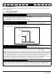
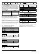
Pr 00.008 {05.009} Motor Rated Voltage Defines the voltage applied to the motor at rated frequency
Pr 00.039 {05.006} Motor Rated Frequency Defines the frequency at which rated voltage is applied
The Motor Rated Voltage (00.008) and the Motor Rated Frequency (00.039) are used to define the voltage to frequency characteristic applied to the
motor (see Control Mode, later in this table). The Motor Rated Frequency is also used in conjunction with the motor rated speed to calculate the
rated slip for slip compensation (see Motor Rated Speed, later in this table).
Pr 00.007 {05.008} Motor Rated Speed Defines the full load rated speed of the motor
Pr 00.040 {05.011} Number of Motor Poles Defines the number of motor poles
The motor rated speed and the number of poles are used with the motor rated frequency to calculate the rated slip of induction machines in Hz.
Rated slip (Hz) = Motor rated frequency - (Number of pole pairs x [Motor rated speed / 60]) =
If Pr 00.007 is set to 0 or to synchronous speed, slip compensation is disabled. If slip compensation is required this parameter should be set to the
nameplate value, which should give the correct rpm for a hot machine. Sometimes it will be necessary to adjust this when the drive is commissioned
because the nameplate value may be inaccurate. Slip compensation will operate correctly both below base speed and within the field-weakening
region. Slip compensation is normally used to correct for the motor speed to prevent speed variation with load. The rated load rpm can be set higher
than synchronous speed to deliberately introduce speed droop. This can be useful to aid load sharing with mechanically coupled motors.
Pr 00.040 is also used in the calculation of the motor speed display by the drive for a given output frequency. When Pr 00.040 is set to ‘Auto’, the
number of motor poles is automatically calculated from the rated frequency Pr 00.039, and the motor rated speed Pr 00.007.
Number of poles = 120 x (Rated Frequency (00.039) / Rated Speed (00.007)) rounded to the nearest even number.
Pr 00.043 {05.010} Motor Rated Power Factor Defines the angle between the motor voltage and current
The power factor is the true power factor of the motor, i.e. the angle between the motor voltage and current. The power factor is used in conjunction
with the Motor Rated Current (00.006), to calculate the rated active current and magnetising current of the motor. The rated active current is used
extensively to control the drive, and the magnetising current is used in vector mode stator resistance compensation. It is important that this
parameter is set up correctly. The drive can measure the motor rated power factor by performing a rotating autotune (see Autotune (Pr 00.038),
below).
Output
voltage
Pr / 2
00.008
Pr
00.008
Pr / 2
00.039
Pr
00.039
Output
frequency
Output voltage characteristic
00.039
00.040
2
------------------
00.007
60
------------------
×
⎝⎠
⎛⎞
=