
User guide


Safety
information
Product
information
Mechanical
installation
Electrical
installation
Getting
started
Basic
parameters
Running the
motor
Optimization NV Media Card
Advanced
parameters
Technical
data
Diagnostics
UL listing
information
62 Unidrive M100 User Guide
Issue Number: 1
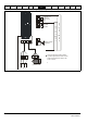
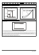
Figure 7-1 Minimum connections to get the motor running in any operating mode
L1 L2 L3
Fuses
L1 L2 L3
U
VW
UVW
10
11
12
13
9
+
BR
+10 V
24 V
Run FWD
Drive enable
Run REV
Braking resistor
(optional)
Induction motor
4
2
1
Frequency
Reference
input
0 V
1
1
T
e
r
m
i
n
a
l
M
o
d
e
K
e
y
p
a
d
M
o
d
e
Thermal overload for braking resistor
to protect against fire risk. This must be
wired to interrupt the AC supply in the
event of a fault.