
User guide

Safety
information
Product
information
Mechanical
installation
Electrical
installation
Getting
started
Basic
parameters
Running the
motor
Optimization NV Media Card
Advanced
parameters
Technical
data
Diagnostics
UL listing
information
Unidrive M100 User Guide 49
Issue Number: 1
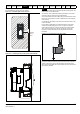
9 +24 V user output
Default function Supply for external digital devices
Voltage tolerance ±20 %
Maximum output current 100 mA
Protection Current limit and trip
10 Digital I/O 1
Default function AT ZERO FREQUENCY output
Type
Positive logic digital input, positive logic voltage source output.
PWM or frequency output modes can be selected.
Input / output mode controlled by … Pr 08.031
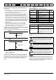
Operating as in input
Absolute maximum applied voltage range -8 V to +30 V relative to 0 V
Impedance 6.8 k
Input threshold 10 V ±0.8 V from IEC 61131-2
Operating as an output
Nominal maximum output current 50 mA
Maximum output current 100 mA (total including +24 Vout)
Common to all modes
Voltage range 0 V to +24 V
Sample / update period 2 ms when routed to destinations Pr 06.035 or Pr 06.036, otherwise 6 ms
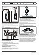
11 Digital Input 2
12 Digital Input 3
13 Digital Input 4
Terminal 11 default function DRIVE ENABLE input
Terminal 12 default function RUN FORWARD input
Terminal 13 default function RUN REVERSE input
Type Positive logic only digital inputs
Voltage range 0 V to +24 V
Absolute maximum applied voltage range -18 V to +30 V relative to 0 V
Impedance 6.8 k
Input threshold 10 V ±0.8 V from IEC 61131-2
Sample / update period 2 ms when routed to destinations Pr 06.035 or Pr 06.036, otherwise 6 ms.
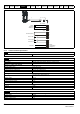
41
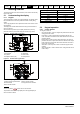
Relay contacts
42
Default function Drive OK indicator
Contact voltage rating 240 Vac, Installation over-voltage category II
Contact maximum current rating
2 A AC 240 V
4 A DC 30 V resistive load
0.5 A DC 30 V inductive load (L/R = 40 ms)
Contact minimum recommended rating 12 V 100 mA
Contact type Normally open
Default contact condition Closed when power applied and drive OK
Update period 4 ms
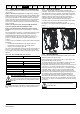
To prevent the risk of a fire hazard in the event of a fault, a fuse or other over-current protection must be installed in the relay circuit.
WARNING