
User guide

Safety
information
Product
information
Mechanical
installation
Electrical
installation
Getting
started
Basic
parameters
Running the
motor
Optimization NV Media Card
Advanced
parameters
Technical
data
Diagnostics
UL listing
information
Unidrive M100 User Guide 47
Issue Number: 1
As a general rule, if the circuits are to pass outside the building where
the drive is located, or if cable runs within a building exceed 30 m, some
additional precautions are advisable. One of the following techniques
should be used:
1. Galvanic isolation, i.e. do not connect the control 0 V terminal to
ground. Avoid loops in the control wiring, i.e. ensure every control
wire is accompanied by its return (0 V) wire.
2. Shielded cable with additional power ground bonding. The cable
shield may be connected to ground at both ends, but in addition the
ground conductors at both ends of the cable must be bonded
together by a power ground cable (equipotential bonding cable) with
cross-sectional area of at least 10 mm
2
, or 10 times the area of the
signal cable shield, or to suit the electrical safety requirements of the
plant. This ensures that fault or surge current passes mainly through
the ground cable and not in the signal cable shield. If the building or
plant has a well-designed common bonded network this precaution
is not necessary.
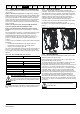
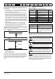
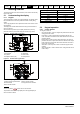
3. Additional over-voltage suppression - for the analog and digital
inputs and outputs, a zener diode network or a commercially
available surge suppressor may be connected in parallel with the
input circuit as shown in Figure 4-25 and Figure 4-26.
If a digital port experiences a severe surge its protective trip may operate
(O.Ld1 trip). For continued operation after such an event, the trip can be
reset automatically by setting Pr 10.034 to 5.
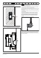
Figure 4-25 Surge suppression for digital and unipolar inputs and
outputs
Figure 4-26 Surge suppression for analog and bipolar inputs and
outputs
Surge suppression devices are available as rail-mounting modules, e.g.
from Phoenix Contact:
Unipolar TT-UKK5-D/24 DC
Bipolar TT-UKK5-D/24 AC
These devices are not suitable for encoder signals or fast digital data
networks because the capacitance of the diodes adversely affects the
signal. Most encoders have galvanic isolation of the signal circuit from
the motor frame, in which case no precautions are required. For data
networks, follow the specific recommendations for the particular
network.
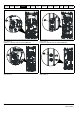
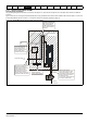
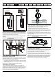
4.8 Control connections
4.8.1 General
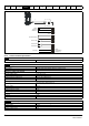
Table 4-15 The control connections consist of:
Key:
All analog terminal functions can be programmed in menu 7.
All digital terminal functions (including the relay) can be programmed in
menu 8.
N
Any signal cables which are carried inside the motor cable (i.e. motor
thermistor, motor brake) will pick up large pulse currents via the cable
capacitance. The shield of these signal cables must be connected to
ground close to the point of exit of the motor cable, to avoid this noise
current spreading through the control system.
Signal from plant Signal to drive
0V 0V
30V zener diode
e.g. 2xBZW50-15
Signal from plant Signal to drive
0V 0V
2 x 15V zener diode
e.g. 2xBZW50-15
Function Qty Control parameters available
Terminal
number
Single ended analog
input
1
Mode, offset, invert, scaling,
destination
2
Digital input 3 Destination, invert 11, 12, 13
Digital input / output 1
Input / output mode select,
destination / source, invert
10
Relay 1 Source, invert 41, 42
Drive enable 1 11
+10 V User output 1 4
+24 V User output 1 9
0V common 1 1
Destination parameter:
Indicates the parameter which is being controlled
by the terminal / function
Source parameter:
Indicates the parameter being output by the
terminal
Mode parameter:
Analog - indicates the mode of operation of the
terminal, i.e. voltage 0-10 V, current 4-20 mA etc.
Digital - indicates the mode of operation of the
terminal, (the Drive Enable terminal is fixed in
positive logic).
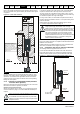
The control circuits are isolated from the power circuits in the
drive by basic insulation (single insulation) only. The installer
must ensure that the external control circuits are insulated
from human contact by at least one layer of insulation
(supplementary insulation) rated for use at the AC supply
voltage.
If the control circuits are to be connected to other circuits
classified as Safety Extra Low Voltage (SELV) (e.g. to a
personal computer), an additional isolating barrier must be
included in order to maintain the SELV classification.
If any of the digital inputs (including the drive enable input)
are connected in parallel with an inductive load (i.e.
contactor or motor brake) then suitable suppression (i.e.
diode or varistor) should be used on the coil of the load. If no
suppression is used then over voltage spikes can cause
damage to the digital inputs and outputs on the drive.
WARNING
WARNING
CAUTION
NOTE