
User guide

Safety
information
Product
information
Mechanical
installation
Electrical
installation
Getting
started
Basic
parameters
Running the
motor
Optimization NV Media Card
Advanced
parameters
Technical
data
Diagnostics
UL listing
information
Unidrive M100 User Guide 45
Issue Number: 1
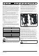
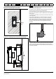
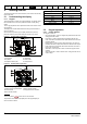
Avoid placing sensitive signal circuits in a zone 300 mm (12 in) in the
area immediately surrounding the power module.
Figure 4-18 Sensitive signal circuit clearance
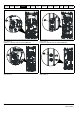
Ensure good EMC grounding.
Figure 4-19 Grounding the drive, motor cable shield and filter
1 Ensure direct metal contact at the drive and filter mounting points. Any
paint must be removed beforehand.
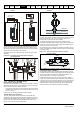
The unbroken motor cable shield (unbroken) electrically connected to
and held in place by means of the grounding bracket.
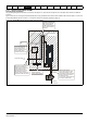
Connect the shield of the motor cable to the ground terminal of the motor
frame using a jumper that is as short as possible and not exceeding 50
mm (2 in) long.
A complete 360
°
termination of the shield to the terminal housing of the
motor is beneficial.
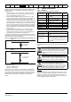
From an EMC consideration it is irrelevant whether the motor cable
contains an internal (safety) ground core, or if there is a separate
external ground conductor, or where grounding is through the shield
alone. An internal ground core will carry a high noise current and
therefore it must be terminated as close as possible to the shield
termination.
Figure 4-20 Grounding the motor cable shield
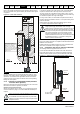
Unshielded wiring to the optional braking resistor(s) may be used
provided the wiring runs internally to the enclosure. Ensure a minimum
spacing of 300 mm (12 in) from the signal wiring and the AC supply
wiring to the external EMC filter. If this condition cannot be met then the
wiring must be shielded.
Sensitive
signal
cable
≥
300 mm
(12 in)
1
NOTE