
User guide

Safety
information
Product
information
Mechanical
installation
Electrical
installation
Getting
started
Basic
parameters
Running the
motor
Optimization NV Media Card
Advanced
parameters
Technical
data
Diagnostics
UL listing
information
44 Unidrive M100 User Guide
Issue Number: 1
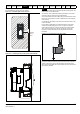
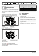
Cable layout
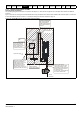
Figure 4-16 indicates the clearances which should be observed around
the drive and related ‘noisy’ power cables by all sensitive control signals
/ equipment.
Figure 4-16 Drive cable clearances
N
Any signal cables which are carried inside the motor cable (i.e. motor
thermistor, motor brake) will pick up large pulse currents via the cable
capacitance. The shield of these signal cables must be connected to
ground close to the motor cable, to avoid this noise current spreading
through the control system.
4.7.4 Compliance with EN 61800-3:2004 (standard
for Power Drive Systems)
Meeting the requirements of this standard depends on the environment
that the drive is intended to operate in, as follows:
Operation in the first environment
Observe the guidelines given in section 4.7.5 Compliance with generic
emission standards on page 44. An external EMC filter will always be
required.
Operation in the second environment
In all cases a shielded motor cable must be used, and an EMC filter is
required for all drives with a rated input current of less than 100 A.
The drive contains an in-built filter for basic emission control. In some
cases feeding the motor cables (U, V and W) once through a ferrite ring
can maintain compliance for longer cable lengths.
For longer motor cables, an external filter is required. Where a filter is
required, follow the guidelines in Section 4.7.5 Compliance with generic
emission standards .
Where a filter is not required, follow the guidelines given in section
4.7.3 General requirements for EMC on page 43.
Refer to section 11.1.25 Electromagnetic compatibility (EMC) on
page 118 for further information on compliance with EMC standards and
definitions of environments.
Detailed instructions and EMC information are given in the EMC Data
Sheet which is available from the supplier of the drive.
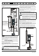
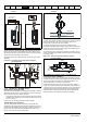
4.7.5 Compliance with generic emission standards
The following information applies to frame sizes 1 to 4.
Use the recommended filter and shielded motor cable. Observe the
layout rules given in Figure 4-17. Ensure the AC supply and ground
cables are at least 100 mm from the power module and motor cable.
Figure 4-17 Supply and ground cable clearance (sizes 1 to 4)
This is a product of the restricted distribution class according
to IEC 61800-3
In a residential environment this product may cause radio
interference in which case the user may be required to take
adequate measures.
Optional braking resistor and overload
Do not place sensitive
(unscreened) signal circuits
within a zone extending
300 mm (12 in)
around the
Drive, motor cable, or input
cable from the EMC filter and
unshielded braking resistor
cable (if used)
300 mm
(12 in)
NOTE
CAUTION
The second environment typically includes an industrial low-
voltage power supply network which does not supply
buildings used for residential purposes. Operating the drive in
this environment without an external EMC filter may cause
interference to nearby electronic equipment whose sensitivity
has not been appreciated. The user must take remedial
measures if this situation arises. If the consequences of
unexpected disturbances are severe, it is recommended that
the guidelines in Section 4.7.5 Compliance with generic
emission standards be adhered to.
CAUTION
≥
100 mm
(4 in)
≥
100 mm
(4 in)
Do not modify
the filter wires