
User guide

Safety
information
Product
information
Mechanical
installation
Electrical
installation
Getting
started
Basic
parameters
Running the
motor
Optimization NV Media Card
Advanced
parameters
Technical
data
Diagnostics
UL listing
information
Unidrive M100 User Guide 41
Issue Number: 1
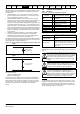
4.7 EMC (Electromagnetic compatibility)
The requirements for EMC are divided into three levels in the following
three sections:
Section 4.10.3, General requirements for all applications, to ensure
reliable operation of the drive and minimise the risk of disturbing nearby
equipment. The immunity standards specified in Chapter 11 Technical
data on page 108 will be met, but no specific emission standards are
applied. Note also the special requirements given in Surge immunity of
control circuits - long cables and connections outside a building on
page 46 for increased surge immunity of control circuits where control
wiring is extended.
Section 4.7.4, Requirements for meeting the EMC standard for
power drive systems, IEC61800-3 (EN 61800-3:2004).
Section 4.7.5, Requirements for meeting the generic emission
standards for the industrial environment, IEC61000-6-4, EN 61000-6-
4:2007.
The recommendations of section 4.7.3 will usually be sufficient to avoid
causing disturbance to adjacent equipment of industrial quality. If
particularly sensitive equipment is to be used nearby, or in a non-
industrial environment, then the recommendations of section 4.7.4 or
section 4.7.5 should be followed to give reduced radio-frequency
emission.
In order to ensure the installation meets the various emission standards
described in:
• The EMC data sheet available from the supplier of the drive
• The Declaration of Conformity at the front of this manual
• Chapter 11 Technical data on page 108
The correct external EMC filter must be used and all of the guidelines in
section 4.7.3 General requirements for EMC on page 43 and section
4.7.5 Compliance with generic emission standards on page 44 must be
followed.
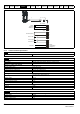
Table 4-14 Drive and EMC filter cross reference
N
The installer of the drive is responsible for ensuring compliance with the
EMC regulations that apply in the country in which the drive is to be
used.
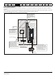
4.7.1 Grounding hardware
The drive is supplied with a grounding bracket to facilitate EMC
compliance. This provides a convenient method for direct grounding of
cable shields without the use of "pig-tails”. Cable shields can be bared
and clamped to the grounding bracket using metal clips or clamps
1
(not
supplied) or cable ties. Note that the shield must in all cases be
continued through the clamp to the intended terminal on the drive, in
accordance with the connection details for the specific signal.
1
A suitable clamp is the Phoenix DIN rail mounted SK14 cable clamp
(for cables with a maximum outer diameter of 14 mm).
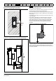
See Figure 4-10 for details regarding the installation of the grounding
bracket.
Figure 4-10 Installation of grounding bracket
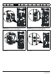
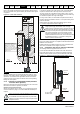
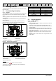
4.7.2 Internal EMC filter
It is recommended that the internal EMC filter be kept in place unless
there is a specific reason for removing it.
If the drive is used as a motoring drive as part of a regen system, then
the internal EMC filter must be removed.
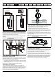
The internal EMC filter reduces radio-frequency emission into the line
power supply. Where the motor cable is short, it permits the
requirements of EN 61800-3:2004 to be met for the second environment
- see section 4.7.4 Compliance with EN 61800-3:2004 (standard for
Power Drive Systems) on page 44 and section 11.1.25 Electromagnetic
compatibility (EMC) on page 118. For longer motor cables the filter
continues to provide a useful reduction in emission levels, and when
used with any length of shielded motor cable up to the limit for the drive,
it is unlikely that nearby industrial equipment will be disturbed. It is
recommended that the filter be used in all applications unless the
instructions given above require it to be removed, or where the ground
leakage current of 28 mA for size 1 is unacceptable. As shown in Figure
4-11 to Figure 4-14 the size 1 internal EMC filter is removed by removing
the screw (1).
Model CT part number
200 V
400 V
High ground leakage current
When an EMC filter is used, a permanent fixed ground
connection must be provided which does not pass through a
connector or flexible power cord. This includes the internal
EMC filter.
WARNING
NOTE
The supply must be disconnected before removing the
internal EMC filter.
WARNING