
User guide


Safety
information
Product
information
Mechanical
installation
Electrical
installation
Getting
started
Basic
parameters
Running the
motor
Optimization NV Media Card
Advanced
parameters
Technical
data
Diagnostics
UL listing
information
40 Unidrive M100 User Guide
Issue Number: 1
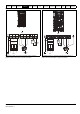
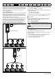
Thermal protection circuit for the braking resistor
The thermal protection circuit must disconnect the AC supply from the
drive if the resistor becomes overloaded due to a fault. Figure 4-9 shows
a typical circuit arrangement.
Figure 4-9 Typical protection circuit for a braking resistor
See Figure 4-1 on page 30 and Figure 4-4 on page 32 for the location of
the +DC and braking resistor connections.
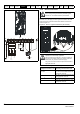
4.5.2 Braking resistor software overload protection
The drive software contains an overload protection function for a braking
resistor. In order to enable and set-up this function, it is necessary to
enter three values into the drive:
• Braking Resistor Rated Power (10.030)
• Braking Resistor Thermal Time Constant (10.031)
• Braking Resistor Resistance (10.061)
This data should be obtained from the manufacturer of the braking
resistors.
Pr 10.039 gives an indication of braking resistor temperature based on a
simple thermal model. Zero indicates the resistor is close to ambient and
100 % is the maximum temperature the resistor can withstand. A ‘Brake
Resistor’ alarm is given if this parameter is above 75 % and the braking
IGBT is active. An It.br trip will occur if Pr 10.039 reaches 100 %, when
Pr 10.037 is set to 0 (default value) or 1.
If Pr 10.037 is equal to 2 or 3, an It.br trip will not occur when Pr 10.039
reaches 100 %, but instead the braking IGBT will be disabled until
Pr 10.039 falls below 95 %. This option is intended for applications with
parallel connected DC buses where there are several braking resistors,
each of which cannot withstand full DC bus voltage continuously. With
this type of application it is unlikely the braking energy will be shared
equally between the resistors because of voltage measurement
tolerances within the individual drives. Therefore with Pr 10.037 set to 2
or 3, then as soon as a resistor has reached its maximum temperature
the drive will disable the braking IGBT, and another resistor on another
drive will take up the braking energy. Once Pr 10.039 has fallen below
95 % the drive will allow the braking IGBT to operate again.
See the Parameter Reference Guide for more information on Pr 10.030,
Pr 10.031, Pr 10.037 and Pr 10.039.
This software overload protection should be used in addition to an
external overload protection device.
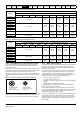
4.6 Ground leakage
The ground leakage current depends upon whether the internal EMC
filter is installed or not. The drive is supplied with the filter installed.
Instructions for removing the internal filter are given in section
4.7.2 Internal EMC filter on page 41.
With internal filter installed:
Size 1: 2.5 mA* AC at 230 V 50 Hz (line to line supply, star point ground)
9.2 mA* AC at 230 V 50 Hz (line to neutral supply, star point
ground)
Size 3: 19.7 mA* AC at 400 V 50 Hz (star point ground)
47.4 mA* AC at 400 V 50 Hz (corner ground)
Size 4: 21 mA* AC at 230 V 50 Hz (3 phase, star point ground)
6.8 mA* AC at 230 V 50 Hz (1 phase, line to line supply, star
point ground)
30 mA* AC at 230 V 50 Hz (1 phase, line to neutral supply, star
point ground)
50 mA* AC at 400 V 50 Hz (3 phase, star point ground)
* Proportional to the supply voltage and frequency.
With internal filter removed:
Size 1: <1.5 mA (line to line supply, star point ground)
<1 mA (line to neutral supply, star point ground)
Size 3: <3.3 mA (star point ground)
<4.9 mA (corner ground)
Size 4: < 3.5 mA (star point ground)
The above leakage currents are just the leakage currents of the drive
with the internal EMC filter connected and do not take into account any
leakage currents of the motor or motor cable.
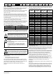
4.6.1 Use of residual current device (RCD)
There are three common types of ELCB / RCD:
1. AC - detects AC fault currents
2. A - detects AC and pulsating DC fault currents (provided the DC
current reaches zero at least once every half cycle)
3. B - detects AC, pulsating DC and smooth DC fault currents
• Type AC should never be used with drives.
• Type A can only be used with single phase drives
• Type B must be used with three phase drives
If an external EMC filter is used, a delay of at least 50 ms should be
incorporated to ensure spurious trips are not seen. The leakage current
is likely to exceed the trip level if all of the phases are not energized
simultaneously.
Optional
EMC
filter
Stop
Start /
Reset
Thermal
protection
device
Braking resistor
Drive
Main contactor
power supply
+DC
BR
When the internal filter is installed the leakage current is
high. In this case a permanent fixed ground connection must
be provided, or other suitable measures taken to prevent a
safety hazard occurring if the connection is lost.
When the leakage current exceeds 3.5 mA, a permanent
fixed ground connection must be provided using two
independent conductors each with a cross-section equal to
or exceeding that of the supply conductors. The drive is
provided with two ground connections to facilitate this. Both
ground connections are necessary to meet EN 61800-5-1:
2007.
Only type B ELCB / RCD are suitable for use with 3 phase
inverter drives.
NOTE
WARNING
WARNING
WARNING