
User guide


Safety
information
Product
information
Mechanical
installation
Electrical
installation
Getting
started
Basic
parameters
Running the
motor
Optimization NV Media Card
Advanced
parameters
Technical
data
Diagnostics
UL listing
information
Unidrive M100 User Guide 39
Issue Number: 1
4.5 Braking
Braking occurs when the drive is decelerating the motor, or is preventing
the motor from gaining speed due to mechanical influences. During
braking, energy is returned to the drive from the motor.
When motor braking is applied by the drive, the maximum regenerated
power that the drive can absorb is equal to the power dissipation
(losses) of the drive.
When the regenerated power is likely to exceed these losses, the DC
bus voltage of the drive increases. Under default conditions, the drive
brakes the motor under PI control, which extends the deceleration time
as necessary in order to prevent the DC bus voltage from rising above a
user defined set-point.
If the drive is expected to rapidly decelerate a load, or to hold back an
overhauling load, a braking resistor must be installed.
Table 4-12 shows the default DC voltage level at which the drive turns on
the braking transistor. However the braking resistor turn on and the turn
off voltages are programmable with Braking IGBT Lower Threshold
(06.073) and Braking IGBT Upper Threshold (06.074).
Table 4-12 Default braking transistor turn on voltage
N
When a braking resistor is used, Pr 02.004 should be set to Fast ramp
mode.
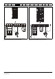
4.5.1 External braking resistor
When a braking resistor is to be mounted outside the enclosure, ensure
that it is mounted in a ventilated metal housing that will perform the
following functions:
• Prevent inadvertent contact with the resistor
• Allow adequate ventilation for the resistor
When compliance with EMC emission standards is required, external
connection requires the cable to be armored or shielded, since it is not
fully contained in a metal enclosure. See section 4.7.5 Compliance with
generic emission standards on page 44 for further details.
Internal connection does not require the cable to be armored or
shielded.
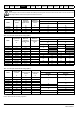
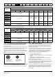
Minimum resistances and power ratings
Table 4-13 Minimum resistance values and peak power rating for
the braking resistor at 40 °C (104 °F)
* Resistor tolerance: ±10 %
For high-inertia loads or under continuous braking, the continuous power
dissipated in the braking resistor may be as high as the power rating of
the drive. The total energy dissipated in the braking resistor is dependent
on the amount of energy to be extracted from the load.
The instantaneous power rating refers to the short-term maximum power
dissipated during the on intervals of the pulse width modulated braking
control cycle. The braking resistor must be able to withstand this
dissipation for short intervals (milliseconds). Higher resistance values
require proportionately lower instantaneous power ratings.
In most applications, braking occurs only occasionally. This allows the
continuous power rating of the braking resistor to be much lower than
the power rating of the drive. It is therefore essential that the
instantaneous power rating and energy rating of the braking resistor are
sufficient for the most extreme braking duty that is likely to be
encountered.
Optimization of the braking resistor requires careful consideration of the
braking duty.
Select a value of resistance for the braking resistor that is not less than
the specified minimum resistance. Larger resistance values may give a
cost saving, as well as a safety benefit in the event of a fault in the
braking system. Braking capability will then be reduced, which could
cause the drive to trip during braking if the value chosen is too large.
Drive voltage rating DC bus voltage level
100 & 200 V 390 V
400 V 780 V
High temperatures
Braking resistors can reach high temperatures. Locate
braking resistors so that damage cannot result. Use cable
having insulation capable of withstanding high temperatures.
Braking resistor overload protection parameter settings
Failure to observe the following information may damage
the resistor.
The drive software contains an overload protection function
for a braking resistor.
For more information on the braking resistor software
overload protection, see Pr 10.030, Pr 10.031 and
Pr 10.061 full descriptions in the Parameter Reference
Guide.
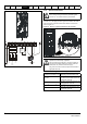
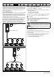
Overload protection
When an external braking resistor is used, it is essential that
an overload protection device is incorporated in the braking
resistor circuit; this is described in Figure 4-9 on page 40.
NOTE
WARNING
CAUTION
WARNING
Model
Minimum
resistance*
Ω
Instantaneous
power rating
kW
Continuous
power rating
kW
100 V
01100017 130 1.2
01100024 130 1.2
02100042 68 2.2
02100056 68 2.2
200 V
01200017 130 1.2
01200024 130 1.2
01200033 130 1.2
01200042 130 1.2
02200024 68 2.2
02200033 68 2.2
02200042 68 2.2
02200056 68 2.2
02200075 68 2.2
03200100 45 3.4
04200133 22 6.9
04200176 22 6.9
400 V
02400013 270 2.3
02400018 270 2.3
02400023 270 2.3
02400032 270 2.3
02400041 270 2.3
03400056 100 6.1
03400073 100 6.1
03400094 100 6.1
04400135 50 12.2
04400170 50 12.2