
User guide


Safety
information
Product
information
Mechanical
installation
Electrical
installation
Getting
started
Basic
parameters
Running the
motor
Optimization NV Media Card
Advanced
parameters
Technical
data
Diagnostics
UL listing
information
38 Unidrive M100 User Guide
Issue Number: 1
If it is not practical to use an inverter-rated motor, an output choke
(inductor) should be used. The recommended type is a simple iron-cored
component with a reactance of about 2 %. The exact value is not critical.
This operates in conjunction with the capacitance of the motor cable to
increase the rise-time of the motor terminal voltage and prevent
excessive electrical stress.
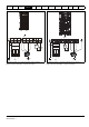
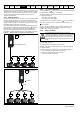
4.4.4 Multiple motors
If the drive is to control more than one motor, one of the fixed V/F modes
should be selected (Pr 05.014 = Fixed or Squared). Make the motor
connections as shown in Figure 4-7 and Figure 4-8. The maximum cable
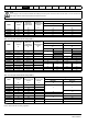
lengths in Table 4-9, Table 4-10 and Table 4-11 apply to the sum of the
total cable lengths from the drive to each motor.
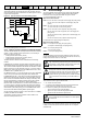
It is recommended that each motor is connected through a protection relay
since the drive cannot protect each motor individually. For
connection, a
sinusoidal filter or an output inductor must be connected as shown in
Figure 4-8, even when the cable lengths are less than the maximum
permissible. For details of inductor sizes refer to the supplier of the drive.
Figure 4-7 Preferred chain connection for multiple motors
Figure 4-8 Alternative connection for multiple motors
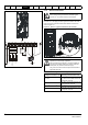
4.4.5 / Δ motor operation
The voltage rating for
and Δ connections of the motor should always
be checked before attempting to run the motor.
The default setting of the motor rated voltage parameter is the same as
the drive rated voltage, i.e.
400 V drive 400 V rated voltage
230 V drive 230 V rated voltage
A typical 3 phase motor would be connected in
for 400 V operation or
Δ for 230 V operation, however, variations on this are common e.g.
690 V
Δ 400 V.
Incorrect connection of the windings will cause severe under or over
fluxing of the motor, leading to a very poor output torque or motor
saturation and overheating respectively.
4.4.6 Output contactor
A contactor is sometimes required to be installed between the drive and
motor for safety purposes.
The recommended motor contactor is the AC3 type.
Switching of an output contactor should only occur when the output of
the drive is disabled.
Opening or closing of the contactor with the drive enabled will lead to:
1. OI ac trips (which cannot be reset for 10 seconds)
2. High levels of radio frequency noise emission
3. Increased contactor wear and tear
Motor protection
relay
Chain connection (preferred)
connection
Inductor
Motor protection
relay
If the cable between the drive and the motor is to be
interrupted by a contactor or circuit breaker, ensure that the
drive is disabled before the contactor or circuit breaker is
opened or closed. Severe arcing may occur if this circuit is
interrupted with the motor running at high current and low
speed.
WARNING