
User guide


Safety
information
Product
information
Mechanical
installation
Electrical
installation
Getting
started
Basic
parameters
Running the
motor
Optimization NV Media Card
Advanced
parameters
Technical
data
Diagnostics
UL listing
information
32 Unidrive M100 User Guide
Issue Number: 1
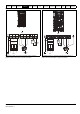
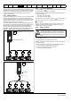
Figure 4-4 Size 4 power connections
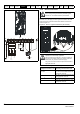
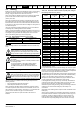
4.1.2 Ground connections
Size 1 to 4
On sizes 1 to 4, the supply and motor ground connections are made
using the ground connections located at the bottom of the drive as
shown in Figure 4-5.
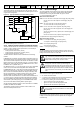
Figure 4-5 Size 1 to 4 ground connections (size 2 shown)
1: 4 x M4 threaded holes for the ground connection.
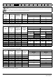
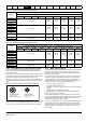
Table 4-1 Protective ground cable ratings
L1 L2
L2L1 L3
Optional EMC
filter
Optional
line reactor
Fuses
L3
Mains
Supply
Supply
Ground
PE UV
W
Motor
Optional ground
connection
+BR
Optional
braking
resistor
Thermal
overload
protection
device
Internal
EMC
filter
Electrochemical corrosion of grounding terminals
Ensure that grounding terminals are protected against
corrosion i.e. as could be caused by condensation.
The ground loop impedance must conform to the
requirements of local safety regulations.
The drive must be grounded by a connection capable of
carrying the prospective fault current until the protective
device (fuse, etc.) disconnects the AC supply.
The ground connections must be inspected and tested at
appropriate intervals.
Input phase conductor size Minimum ground conductor size
10 mm
2
Either 10 mm
2
or two conductors of
the same cross-sectional area as the
input phase conductor.
> 10 mm
2
and 16 mm
2
The same cross-sectional area as the
first input phase conductor.
> 16 mm
2
and 35 mm
2
16 mm
2
> 35 mm
2
Half of the cross-sectional area of the
input phase conductor.
WARNING
1
WARNING