
User guide

Safety
information
Product
information
Mechanical
installation
Electrical
installation
Getting
started
Basic
parameters
Running the
motor
Optimization NV Media Card
Advanced
parameters
Technical
data
Diagnostics
UL listing
information
28 Unidrive M100 User Guide
Issue Number: 1
3.9 Electrical terminals
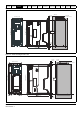
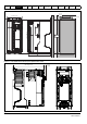
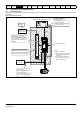
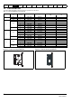
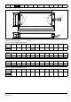
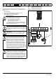
3.9.1 Location of the power and ground terminals
Figure 3-17 Locations of the power and ground terminals
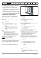
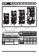
3.9.2 Terminal sizes and torque settings
Table 3-6 Drive relay terminal data
Table 3-7 Drive power terminal data
Table 3-8 Terminal block maximum cable sizes
Table 3-9 External EMC filter terminal data
1
2
6
3
1
4
8
7
3
5
1
2
1
4
6
6
6
7
8
3
5
4
7
8
5
2
4
3
8
7
2
5
Key:
1. Control terminals 4. AC power terminals 7. DC bus +
2. Relay terminals 5. Motor terminals 8. Brake terminal
3. Ground connections 6. DC bus -
To avoid a fire hazard and maintain validity of the UL listing,
adhere to the specified tightening torques for the power and
ground terminals. Refer to the following tables.
Model Connection type Torque setting
All Screw terminals 0.5 N m (0.4 lb ft)
Model
size
AC terminals DC and braking Ground terminal
1 0.5 N m (0.4 lb ft)
1.5 N m (1.0 lb ft)
2
1.4 N m (1.0 Ib ft)3
4
WARNING
Model size Terminal block description Max cable size
All
Control connector 1.5 mm² (16 AWG)
2 way relay connector 2.5 mm² (12 AWG)
All AC input power connector 6 mm² (10 AWG)
All AC output power connector 2.5 mm² (12 AWG)
CT part
number
Power
connections
Ground
connections
Max cable
size
Max torque
Ground
stud size
Max torque