
User guide


Safety
information
Product
information
Mechanical
installation
Electrical
installation
Getting
started
Basic
parameters
Running the
motor
Optimization NV Media Card
Advanced
parameters
Technical
data
Diagnostics
UL listing
information
Unidrive M100 User Guide 127
Issue Number: 1
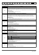
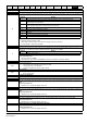
HF16 Data processing error: RTOS error
The HF16 trip indicates that a RTOS error has occurred. This trip indicates that the control PCB on the drive has failed.
Recommended actions:
• Hardware fault – Contact the supplier of the drive
HF17 Data processing error: Clock supplied to the control board is out of specification
The HF17 trip indicates that the clock supplied to the control board logic is out of specification. This trip indicates that the
control PCB on the drive has failed.
Recommended actions:
• Hardware fault – Contact the supplier of the drive
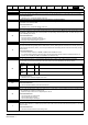
It.Ac
Output current overload timed out (I
2
t)
20
The It.Ac trip indicates a motor thermal overload based on the output current (Pr 05.007) and motor thermal time constant
(Pr 04.015). Pr 04.019 displays the motor temperature as a percentage of the maximum value. The drive will trip on It.Ac
when Pr 04.019 gets to 100 %.
Recommended actions:
• Ensure the load is not jammed / sticking
• Check the load on the motor has not changed
• Ensure the motor rated current is not zero
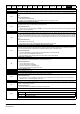
It.br
Braking resistor overload timed out (I
2
t)
19
The It.br trip indicates that braking resistor overload has timed out. The value in Braking Resistor Thermal Accumulator
(10.039) is calculated using Braking Resistor Rated Power (10.030), Braking Resistor Thermal Time Constant (10.031) and
Braking Resistor Resistance (10.061). The It.br trip is initiated when the Braking Resistor Thermal Accumulator (10.039)
reaches 100 %.
Recommended actions:
• Ensure the values entered in Pr 10.030, Pr 10.031 and Pr 10.061 are correct
• If an external thermal protection device is being used and the braking resistor software overload protection is not
required, set Pr 10.030, Pr 10.031 or Pr 10.061 to 0 to disable the trip.
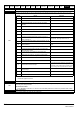
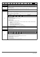
LF.Er Communication has been lost / errors detected between power, control and rectifier modules
90
This trip is initiated if there is no communications between power, control or the rectifier module or if excessive
communication errors have been detected. The reason for the trip can be identified by the sub-trip number.
Recommended actions:
• Hardware fault - contact the supplier of the drive.
no.PS No power board
236
No communication between the power and control boards.
Recommended actions:
• Check connection between power and control board.
O.Ld1 Digital output overload
26
The O.Ld1 trip indicates that the total current drawn from 24 V user supply or from the digital output has exceeded the limit.
A trip is initiated if the following condition is met:
• Maximum output current from one digital output is 100 mA.
Recommended actions:
• Check total loads on digital outputs
• Check control wiring is correct
• Check output wiring is undamaged
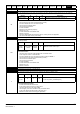
O.SPd Motor frequency has exceeded the over frequency threshold
7
In open-loop mode, if the Post-ramp Reference (02.001) exceeds the threshold set in the Over Frequency Threshold
(03.008) in either direction, an O.SPd trip is produced. If Pr 3.008 is set to 0.00 the threshold is then equal to 1.2 x the value
set in Pr 1.006.
Recommended actions:
• Check that a mechanical load is not driving motor'
Trip Diagnosis
Source xx y zz
Control
system
00 0 01: No communications between the control system and the power system.
Control
system
00 0 02: Excessive communication errors between the control system and power system.
Control
system
01 1 00: Excessive communications errors detected by the rectifier module.