
User guide


Safety
information
Product
information
Mechanical
installation
Electrical
installation
Getting
started
Basic
parameters
Running the
motor
Optimization NV Media Card
Advanced
parameters
Technical
data
Diagnostics
UL listing
information
118 Unidrive M100 User Guide
Issue Number: 1
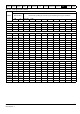
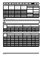
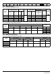
11.1.23 Braking resistor values
Table 11-21 Minimum resistance values and peak power rating for
the braking resistor at 40 °C (104 °F)
* Resistor tolerance: ±10 %
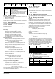
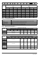
11.1.24 Torque settings
Table 11-22 Drive relay terminal data
Table 11-23 Drive power terminal data
Table 11-24 Terminal block maximum cable sizes
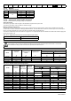
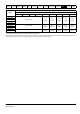
11.1.25 Electromagnetic compatibility (EMC)
This is a summary of the EMC performance of the drive. For full details,
refer to the EMC Data Sheet which can be obtained from the supplier of
the drive.
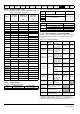
Table 11-25 Immunity compliance
1
See section Surge immunity of control circuits - long cables and
connections outside a building on page 46 for control ports for possible
requirements regarding grounding and external surge protection
Model
Minimum
resistance *
Instantaneous
power rating
Continuous
power rating
Ω kW kW
100 V
01100017 130 1.2
01100024 130 1.2
02100042 130 1.2
02100056 130 1.2
200 V
01200017 130 1.2
01200024 130 1.2
01200033 130 1.2
01200042 130 1.2
02200024 68 2.2
02200033 68 2.2
02200042 68 2.2
02200056 68 2.2
02200075 68 2.2
03200100 45 3.4
04200133 22 6.9
04200176 22 6.9
400 V
02400013 270 2.3
02400018 270 2.3
02400023 270 2.3
02400032 270 2.3
02400041 270 2.3
03400056 100 6.1
03400073 100 6.1
03400094 100 6.1
04400135 50 12.2
04400170 50 12.2
Model Connection type Torque setting
All Screw terminals 0.5 N m (0.4 lb ft)
Model
size
AC terminals DC and braking Ground terminal
1 0.5 Nm (0.4 lb ft)
1.5 N m (1.0 lb ft)
2
1.4 Nm (1 lb ft)3
4
Model size Terminal block description Max cable size
All
Control connector 1.5 mm² (16 AWG)
2 way relay connector 2.5 mm² (12 AWG)
All AC input power connector 6 mm² (10 AWG)
All AC output power connector 2.5 mm² (12 AWG)
Standard
Type of
immunity
Test specification Application Level
IEC61000-4-2
EN61000-4-2
Electrostatic
discharge
6 kV contact
discharge
8 kV air discharge
Module
enclosure
Level 3
(industrial)
IEC61000-4-3
EN61000-4-3
Radio
frequency
radiated field
10 V/m prior to
modulation
80 - 1000 MHz
80 % AM (1 kHz)
modulation
Module
enclosure
Level 3
(industrial)
IEC61000-4-4
EN61000-4-4
Fast transient
burst
5/50 ns 2 kV
transient at 5 kHz
repetition frequency
via coupling clamp
Control lines
Level 4
(industrial
harsh)
5/50 ns 2 kV
transient at 5 kHz
repetition frequency
by direct injection
Power lines
Level 3
(industrial)
IEC61000-4-5
EN61000-4-5
Surges
Common mode 4 kV
1.2/50 μs
waveshape
AC supply
lines:
line to ground
Level 4
Differential mode
2 kV
1.2/50 μs
waveshape
AC supply
lines:
line to line
Level 3
Lines to ground
Signal ports
to ground
1
Level 2
IEC61000-4-6
EN61000-4-6
Conducted
radio
frequency
10V prior to
modulation
0.15 - 80 MHz
80 % AM (1 kHz)
modulation
Control and
power lines
Level 3
(industrial)
IEC61000-4-11
EN61000-4-11
Voltage dips
and
interruptions
-30 % 10 ms
+60 % 100 ms
-60 % 1 s
<-95 % 5 s
AC power
ports
IEC61000-6-1
EN61000-6-
1:2007
Generic immunity standard for the
residential, commercial and light -
industrial environment
Complies
IEC61000-6-2
EN61000-6-
2:2005
Generic immunity standard for the
industrial environment
Complies
IEC61800-3
EN61800-
3:2004
Product standard for adjustable
speed power drive systems
(immunity requirements)
Meets immunity
requirements for first and
second environments