
User guide


Safety
information
Product
information
Mechanical
installation
Electrical
installation
Getting
started
Basic
parameters
Running the
motor
Optimization NV Media Card
Advanced
parameters
Technical
data
Diagnostics
UL listing
information
112 Unidrive M100 User Guide
Issue Number: 1
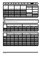
11.1.3 Supply requirements
AC supply voltage:
100 V drive: 100 V to 120 V ±10 %
200 V drive: 200 V to 240 V ±10 %
400 V drive: 380 V to 480 V ±10 %
Number of phases: 3
Maximum supply imbalance: 2 % negative phase sequence (equivalent
to 3 % voltage imbalance between phases).
Frequency range: 48 to 62 Hz
For UL compliance only, the maximum supply symmetrical fault current
must be limited to 100 kA
11.1.4 Line reactors
Input line reactors reduce the risk of damage to the drive resulting from
poor phase balance or severe disturbances on the supply network.
Where line reactors are to be used, reactance values of approximately
2 % are recommended. Higher values may be used if necessary, but
may result in a loss of drive output (reduced torque at high speed)
because of the voltage drop.
For all drive ratings, 2 % line reactors permit drives to be used with a
supply unbalance of up to 3.5 % negative phase sequence (equivalent to
5 % voltage imbalance between phases).
Severe disturbances may be caused by the following factors, for example:
• Power factor correction equipment connected close to the drive.
• Large DC drives having no or inadequate line reactors connected to
the supply.
• Across the line (DOL) started motor(s) connected to the supply such
that when any of these motors are started, the voltage dip exceeds
20 %
Such disturbances may cause excessive peak currents to flow in the
input power circuit of the drive. This may cause nuisance tripping, or in
extreme cases, failure of the drive.
Drives of low power rating may also be susceptible to disturbance when
connected to supplies with a high rated capacity.
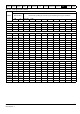
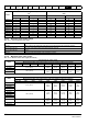
Line reactors are particularly recommended for use with the following
drive models when one of the above factors exists, or when the supply
capacity exceeds 175 kVA:
Model sizes 04200133 to 04400170 have an internal DC choke so they
do not require AC line reactors except for cases of excessive phase
unbalance or extreme supply conditions.
Where required, each drive must have its own reactor(s). Three
individual reactors or a single three-phase reactor should be used.
Reactor current ratings
The current rating of the line reactors should be as follows:
Continuous current rating:
Not less than the continuous input current rating of the drive
Repetitive peak current rating:
Not less than twice the continuous input current rating of the drive
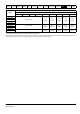
11.1.5 Motor requirements
No. of phases: 3
Maximum voltage:
100 V drive: 240 V
200 V drive: 240 V
400 V drive: 480 V
575 V drive: 575 V
690 V drive: 690 V
11.1.6 Temperature, humidity and cooling method
Ambient temperature operating range:
- 20 °C to 40 °C (- 4 °F to 104 °F).
Output current derating must be applied at ambient temperatures
>40 °C (104 °F).
Cooling method: Forced convection
Maximum humidity: 95 % non-condensing at 40 °C (104 °F)
11.1.7 Storage
-40 °C (-40 °F) to +60 °C (140 °F) for long term storage.
Storage time is 2 years.
Electrolytic capacitors in any electronic product have a storage period
after which they require reforming or replacing.
The DC bus capacitors have a storage period of 10 years.
The low voltage capacitors on the control supplies typically have a
storage period of 2 years and are thus the limiting factor.
Low voltage capacitors cannot be reformed due to their location in the
circuit and thus may require replacing if the drive is stored for a period of
2 years or greater without power being applied.
It is therefore recommended that drives are powered up for a minimum
of 1 hour after every 2 years of storage.
This process allows the drive to be stored for a further 2 years.
11.1.8 Altitude
Altitude range: 0 to 3,000 m (9,900 ft), subject to the following
conditions:
1,000 m to 3,000 m (3,300 ft to 9,900 ft) above sea level: de-rate the
maximum output current from the specified figure by 1% per 100 m
(330 ft) above 1,000 m (3,300 ft)
For example at 3,000 m (9,900 ft) the output current of the drive would
have to be de-rated by 20 %.
11.1.9 IP / UL Rating
The drive is rated to IP20 pollution degree 2 (dry, non-conductive
contamination only).
In addition to this, drive sizes 2 and 3 are rated to IP21 standard (without
an Adaptor Interface module installed).
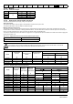
The IP rating of a product is a measure of protection against ingress and
contact to foreign bodies and water. It is stated as IP XX, where the two
digits (XX) indicate the degree of protection provided as shown in Table
11-5.
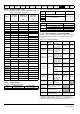
Table 11-5 IP Rating degrees of protection
First digit Second digit
Protection against contact and
ingress of foreign bodies
Protection against ingress of water
0 No protection 0 No protection
1
Protection against large
foreign bodies φ > 50 mm
(large area contact with the
hand)
1
Protection against vertically
falling drops of water
2
Protection against medium
size foreign bodies φ > 12 mm
(finger)
2
Protection against spraywater
(up to 15 ° from the vertical)
3
Protection against small
foreign bodies φ > 2.5 mm
(tools, wires)
3
Protection against spraywater
(up to 60 ° from the vertical)
4
Protection against granular
foreign bodies φ > 1mm (tools,
wires)
4
Protection against splashwater
(from all directions)
5
Protection against dust
deposit, complete protection
against accidental contact.
5
Protection against heavy
splash water (from all
directions, at high pressure)
6
Protection against dust
ingress, complete protection
against accidental contact.
6
Protection against deckwater
(e.g. in heavy seas)
7 - 7 Protection against immersion
8 - 8 Protection against submersion