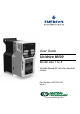
User Guide Unidrive M100 Model size 1 to 4 Variable Speed AC drive for induction motors Part Number: 0478-0041-01 Issue: 1 www.controltechniques.
Original Instructions For the purposes of compliance with the EU Machinery Directive 2006/42/EC General information The manufacturer accepts no liability for any consequences resulting from inappropriate, negligent or incorrect installation or adjustment of the optional operating parameters of the equipment or from mismatching the variable speed drive with the motor. The contents of this guide are believed to be correct at the time of printing.
How to use this guide This user guide provides complete information for installing and operating the drive from start to finish. The information is in logical order, taking the reader from receiving the drive through to fine tuning the performance. NOTE There are specific safety warnings throughout this guide, located in the relevant sections. In addition, Chapter 1 Safety information contains general safety information.
Contents 1 Safety information .................................7 5 1.1 1.2 1.3 1.4 1.5 1.6 1.7 1.8 1.9 1.10 1.11 Warnings, Cautions and Notes .............................7 Electrical safety - general warning ........................7 System design and safety of personnel ................7 Environmental limits ..............................................7 Access ...................................................................7 Fire protection .......................................................
12 Diagnostics ........................................121 12.1 12.2 12.3 12.4 12.5 12.6 12.7 12.8 12.9 Status modes ...................................................121 Trip indications ..................................................121 Identifying a trip / trip source .............................121 Trips, Sub-trip numbers ....................................122 Internal / Hardware trips ....................................134 Alarm indications ...............................................
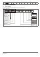
Declaration of Conformity Control Techniques Ltd The Gro Newtown Powys UK SY16 3BE This declaration applies to Unidrive M variable speed drive products, comprising models numbers as shown below: Maaa-bbcddddd Valid characters: aaa 100, 101 bb 02, 03 c ddddd 1, 2 or 4 00013, 00018, 00023, 00024, 00032, 00033, 00041, 00042, 00056, 00075 00056, 00073, 00094, 00100 The AC variable speed drive products listed above have been designed and manufactured in accordance with the following European harmonized sta
Safety Product Mechanical information information installation 1 1.1 Electrical installation Getting started Basic Running the Optimization parameters motor Technical data Diagnostics UL listing information 1.6 Warnings, Cautions and Notes The drive enclosure is not classified as a fire enclosure. A separate fire enclosure must be provided. For further information, refer to section 3.2.5 Fire protection on page 17.
Safety Product Mechanical information information installation Electrical installation 1.10 Electrical installation 1.10.
Safety Product information information Mechanical installation Electrical installation Getting started 2 Product information 2.
Safety Product information information 2.2 Mechanical installation Electrical installation Getting started Basic parameters Running the Optimization motor NV Media Card Advanced Technical parameters data Diagnostics UL listing information Ratings The drive is single rated. The rating is compatible with motors designed to IEC60034. The graph on the right illustrates Heavy Duty with respect to continuous current rating and short term overload limits.
Safety Product information information Mechanical installation Electrical installation Getting started Basic parameters Running the Optimization motor NV Media Card Advanced Technical parameters data UL listing information Diagnostics Table 2-1 100 V drive ratings (100 V to 120 V ±10 %) Heavy Duty Maximum continuous output current Open loop peak current Nominal power at 100 V Motor power at 100 V A A kW hp 01100017 1.7 2.6 0.25 0.
Safety Product information information 2.2.1 Mechanical installation Electrical installation Getting started Basic parameters Running the Optimization motor NV Media Card Advanced Technical parameters data Diagnostics UL listing information Typical short term overload limits The maximum percentage overload limit changes depending on the selected motor. Variations in motor rated current, motor power factor and motor leakage inductance all result in changes in the maximum possible overload.
Safety Product information information 2.4 Mechanical installation Electrical installation Getting started Basic parameters Running the Optimization motor NV Media Card Advanced Technical parameters data Diagnostics UL listing information Drive features Figure 2-2 Features of the drive 2 2 1 3 2 3 1 5 8 5 4 1 7 3 4 6 11 7 11 6 10 8 10 12 12 9 2 2 1 1 3 4 5 4 3 4 5 9 7 3 8 7 8 9 6 11 10 12 6 11 10 12 Key 1. Rating label (On side of drive) 6.
Safety Product information information 2.5 Mechanical installation Electrical installation Getting started Basic parameters Running the Optimization motor NV Media Card Advanced Technical parameters data Diagnostics UL listing information Keypad and display The keypad and display provide information to the user regarding the operating status of the drive and trip codes, and provide the means for changing parameters, stopping and starting the drive, and the ability to perform a drive reset.
Safety Product information information 2.7 Mechanical installation Electrical installation Getting started Basic parameters Running the Optimization motor NV Media Card Advanced Technical parameters data Diagnostics UL listing information Options Figure 2-6 Options available with the drive 1 1.
Safety Product information information Mechanical installation Electrical installation Getting started Basic parameters Running the Optimization motor NV Media Card Advanced Technical parameters data Diagnostics UL listing information Table 2-5 Adaptor Interface (AI) option module identification Type Option module Backup 2.
Safety Product information information 3 Mechanical installation Electrical installation Getting started Basic Running the parameters motor Mechanical installation This chapter describes how to use all mechanical details to install the drive. The drive is intended to be installed in an enclosure. Key features of this chapter include: • • • Enclosure sizing and layout Option module installing Terminal location and torque settings 3.1 WARNING WARNING WARNING 3.
Safety Product information information 3.2.6 Mechanical installation Electrical installation Getting started Basic Running the parameters motor Optimization NV Media Card Advanced parameters Technical data Diagnostics UL listing information Electromagnetic compatibility Variable speed drives are powerful electronic circuits which can cause electromagnetic interference if not installed correctly with careful attention to the layout of the wiring.
Safety Product information information Figure 3-4 Mechanical installation Electrical installation Getting started Basic Running the parameters motor Optimization NV Media Card Advanced parameters Technical data Diagnostics UL listing information Removing the terminal cover 1 2 3 1. Using a flat bladed screwdriver, turn the terminal cover locking clip anti-clockwise by approximately 30° 2. Slide the terminal cover down 3.
Safety Product information information Figure 3-6 Mechanical installation Electrical installation Getting started Basic Running the parameters motor Optimization NV Media Card Advanced parameters Technical data Diagnostics UL listing information Removal of the AI-Backup Adaptor 1 • To remove the AI-Backup adaptor, pull it up away from the drive in the direction shown (1) 3.4 Dimensions and mounting methods The drive is surface mounted.
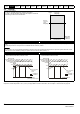
Safety Product information information Figure 3-8 Mechanical installation Electrical installation Getting started Basic Running the parameters motor Optimization NV Media Card Advanced parameters Technical data Diagnostics UL listing information Surface mounting the size 2 drive 75 mm (3.0 in) 180 mm (7.1 in) 205 mm (8.07 in) 11 mm (0.43 in) 5.5 mm (0.22 in) 55 mm (2.20 in) Æ5.0 mm (0.2 in) x 4 holes 194 mm (7.63 in) 5.5 mm (0.22 in) 150 mm (6.
Safety Product information information Figure 3-10 Mechanical installation Electrical installation Getting started Basic Running the parameters motor Optimization NV Media Card Advanced parameters Technical data Diagnostics UL listing information Surface mounting the size 4 drive 14.5 mm (0.57 in) 6.0 mm (0.24 in) 245 mm (9.65 in) 86.0 mm (3.40 in) Æ6.0 mm (0.24 in) x 4 holes 265 mm (10.43 in) 6.0 mm (0.24 in) 277 mm (10.90 in) 115 mm (4.53 in) 175 mm (6.
Safety Product information information Mechanical installation Electrical installation Getting started Basic Running the parameters motor 3.5 Enclosure for standard drives 3.5.1 Enclosure layout Optimization NV Media Card Advanced parameters Technical data Diagnostics UL listing information Please observe the clearances in the diagram below taking into account any appropriate notes for other devices / auxiliary equipment when planning the installation.
Safety Product information information 3.5.2 Mechanical installation Electrical installation Getting started Basic Running the parameters motor Enclosure sizing Optimization Figure 3-13 1. Add the dissipation figures from section 11.1.2 Power dissipation on page 110 for each drive that is to be installed in the enclosure. 2. If an external EMC filter is to be used with each drive, add the dissipation figures from section 11.2.
Safety Product information information Mechanical installation Electrical installation Getting started Basic Running the parameters motor Optimization NV Media Card Advanced parameters Technical data Diagnostics UL listing information Example To calculate the size of an enclosure for the following: • • • • • Three drives operating at the Normal Duty rating External EMC filter for each drive Braking resistors are to be mounted outside the enclosure Maximum ambient temperature inside the enclosure
Safety Product information information 3.8 Mechanical installation Electrical installation Getting started Basic Running the parameters motor Optimization NV Media Card Advanced parameters Technical data Diagnostics UL listing information External EMC filter The external EMC filter details for each drive rating are provided in the table below.
Safety Product information information Figure 3-16 Mechanical installation Electrical installation Getting started Basic Running the parameters motor Optimization NV Media Card Advanced parameters Technical data Diagnostics UL listing information Size 1 to 4 external EMC filter A Y Z Y PE U2 V2 W2 X Last / Load Netz / Line C X W U1 V1 W1 V L1' L2' L3' Z B H D E Z Y V: Ground stud X: Threaded holes for footprint mounting of the drive Z: Bookcase mounting slot diameter.
Safety Product information information Mechanical installation Electrical installation Getting started Basic Running the parameters motor 3.9 Electrical terminals 3.9.1 Location of the power and ground terminals Figure 3-17 Optimization Advanced parameters NV Media Card Technical data Diagnostics UL listing information Locations of the power and ground terminals 2 1 1 2 4 5 2 1 4 2 1 4 4 5 5 5 7 3 6 3 8 8 7 6 3 6 6 3 8 7 8 7 Key: 1. Control terminals 4.
Safety Product information information 3.10 Mechanical installation Electrical installation Getting started Basic Running the parameters motor Optimization NV Media Card Advanced parameters Technical data Diagnostics UL listing information Routine maintenance The drive should be installed in a cool, clean, well ventilated location. Contact with moisture and/or dust with the drive should be avoided.
Safety information 4 Product information Mechanical installation Electrical installation Getting started Basic Running the parameters motor Electrical installation Many cable management features have been incorporated into the product and accessories, this chapter shows how to optimize them. Key features include: • • • • Optimization NV Media Card Advanced parameters Technical Diagnostics data 4.1 Power connections 4.1.
Safety information Figure 4-2 PE L1 Product information Mechanical installation Electrical installation Getting started Basic Running the parameters motor Size 2 power connections L2 L3 U V Optimization NV Media Card Figure 4-3 W Optional EMC filter + Thermal overload protection device Optional line reactor BR PE Technical Diagnostics data UL listing information Size 3 power connections L1 L2 L3 Optional EMC filter - + BR U V W Thermal overload protection device Optional
Safety information Figure 4-4 Product information Mechanical installation Electrical installation Getting started Basic Running the parameters motor Size 4 power connections Optimization NV Media Card 4.1.2 Advanced parameters Technical Diagnostics data UL listing information Ground connections Electrochemical corrosion of grounding terminals Ensure that grounding terminals are protected against corrosion i.e. as could be caused by condensation.
Safety information 4.2 Product information Mechanical installation Electrical installation Getting started Basic Running the parameters motor AC supply requirements Voltage: 100 V drive: 100 V to 120 V ±10 % 200 V drive: 200 V to 240 V ±10 % 400 V drive: 380 V to 480 V ±10 % Number of phases: 3 Maximum supply imbalance: 2 % negative phase sequence (equivalent to 3 % voltage imbalance between phases).
Safety information Product information Mechanical installation Electrical installation Getting started Basic Running the parameters motor Optimization NV Media Card Advanced parameters Technical Diagnostics data UL listing information Fuses WARNING The AC supply to the drive must be installed with suitable protection against overload and short-circuits. Table 4-3 shows recommended fuse ratings. Failure to observe this requirement will cause risk of fire.
Safety information Product information Mechanical installation Electrical installation Getting started Basic Running the parameters motor Optimization NV Media Card Advanced parameters Technical Diagnostics data UL listing information The nominal cable sizes below are only a guide. The mounting and grouping of cables affects their current-carrying capacity, in some cases smaller cables may be acceptable but in other cases a larger cable is required to avoid excessive temperature or voltage drop.
Safety information Product information Mechanical installation Electrical installation Getting started Basic Running the parameters motor Optimization NV Media Card Advanced parameters Technical Diagnostics data UL listing information N NOTE The nominal output cable sizes assume that the motor maximum current matches that of the drive. Where a motor of reduced rating is used the cable rating may be chosen to match that of the motor.
Safety information Product information Table 4-10 Mechanical installation Electrical installation Getting started Basic Running the parameters motor Optimization NV Media Card Advanced parameters Technical Diagnostics data UL listing information Maximum motor cable lengths (200 V drives) 200 V Nominal AC supply voltage Model Maximum permissible motor cable length for each of the following switching frequencies 0.
Safety information Product information Mechanical installation Electrical installation Getting started Basic Running the parameters motor If it is not practical to use an inverter-rated motor, an output choke (inductor) should be used. The recommended type is a simple iron-cored component with a reactance of about 2 %. The exact value is not critical.
Safety information 4.5 Product information Mechanical installation Electrical installation Getting started Basic Running the parameters motor Braking Optimization NV Media Card Advanced parameters Technical Diagnostics data Minimum resistances and power ratings Braking occurs when the drive is decelerating the motor, or is preventing the motor from gaining speed due to mechanical influences. During braking, energy is returned to the drive from the motor.
Safety information Product information Mechanical installation Electrical installation Getting started Basic Running the parameters motor Thermal protection circuit for the braking resistor The thermal protection circuit must disconnect the AC supply from the drive if the resistor becomes overloaded due to a fault. Figure 4-9 shows a typical circuit arrangement. Figure 4-9 Typical protection circuit for a braking resistor Optimization NV Media Card 4.
Safety information 4.7 Product information Mechanical installation Electrical installation Getting started Basic Running the parameters motor EMC (Electromagnetic compatibility) The requirements for EMC are divided into three levels in the following three sections: Section 4.10.3, General requirements for all applications, to ensure reliable operation of the drive and minimise the risk of disturbing nearby equipment.
Safety information Figure 4-11 Product information Mechanical installation Electrical installation Getting started Basic Running the parameters motor Removal of the size 1 internal EMC filter Figure 4-13 Advanced parameters Technical Diagnostics data UL listing information Removal of the size 3 internal EMC filter 1 1 To electrically disconnect the internal EMC filter, remove the screw as shown above (1).
Safety information 4.7.3 Product information Mechanical installation Electrical installation Getting started Basic Running the parameters motor Optimization NV Media Card Advanced parameters Technical Diagnostics data UL listing information General requirements for EMC Ground (earth) connections The grounding arrangements should be in accordance with Figure 4-15, which shows a single drive on a back-plate with or without an additional enclosure.
Safety information Product information Mechanical installation Electrical installation Getting started Basic Running the parameters motor Cable layout Figure 4-16 indicates the clearances which should be observed around the drive and related ‘noisy’ power cables by all sensitive control signals / equipment.
Safety information Product information Mechanical installation Electrical installation Getting started Basic Running the parameters motor Avoid placing sensitive signal circuits in a zone 300 mm (12 in) in the area immediately surrounding the power module. Figure 4-18 Sensitive signal circuit clearance Optimization NV Media Card Advanced parameters Technical Diagnostics data UL listing information NOTE 1 Ensure direct metal contact at the drive and filter mounting points.
Safety information Figure 4-21 Product information Mechanical installation Electrical installation Getting started Basic Running the parameters motor Shielding requirements of optional external braking resistor Optimization NV Media Card Figure 4-23 Advanced parameters Technical Diagnostics data UL listing information Connecting the motor cable to a terminal block in the enclosure Optional external braking resistor From the Drive Optional external braking resistor Enclosure Enclosure BR
Safety information Product information Mechanical installation Electrical installation Getting started Basic Running the parameters motor As a general rule, if the circuits are to pass outside the building where the drive is located, or if cable runs within a building exceed 30 m, some additional precautions are advisable. One of the following techniques should be used: 1. Galvanic isolation, i.e. do not connect the control 0 V terminal to ground. Avoid loops in the control wiring, i.e.
Safety information Product information Figure 4-27 Mechanical installation Electrical installation Getting started Basic Running the parameters motor Optimization NV Media Card Advanced parameters Technical Diagnostics data UL listing information Default terminal functions 14 1 41 42 0V common 1 Analog frequency reference 1 2 +10 V +24 V 1 9 At zero frequency 10 Drive enable 11 Run forward 12 Run reverse 13 Drive OK 4.8.
Safety information 9 Product information Mechanical installation Electrical installation Getting started Basic Running the parameters motor Optimization NV Media Card Advanced parameters Technical Diagnostics data UL listing information +24 V user output Default function Supply for external digital devices Voltage tolerance ±20 % Maximum output current 100 mA Protection Current limit and trip 10 Digital I/O 1 Default function AT ZERO FREQUENCY output Type Positive logic digital inpu
Safety information 5 Product information Mechanical installation Electrical installation Getting started Basic parameters Getting started Running the Optimization motor Table 5-3 5.1.1 Advanced parameters Understanding the display Keypad The keypad display consists of a 6 digit LED display. The display shows the drive status or the menu and parameter number currently being edited. The mm.ppp signifies the menu parameter number of the drive’s menus and parameter. 100.99 31.12.11 or 12.31.
Safety information Figure 5-3 Product information Mechanical installation Electrical installation Getting started Basic parameters Running the Optimization motor NV Media Card Advanced parameters Technical Diagnostics data UL listing information Display modes Status If Drive Status (Pr 10.101) = 4 (Run) Show value only If Drive Status (Pr 10.101) <> 4 Show status only or Timeout 240 s or hold Press and release to go back to status Press and release.
Safety information Product information Mechanical installation Electrical installation Getting started Basic parameters 5.3 NOTE The up and down buttons can only be used to move between menus if Pr 00.010 has been set to show 'ALL'. Refer to section 5.8 Parameter access level and security on page 54.
Safety information 5.5 Product information Mechanical installation Electrical installation Getting started Basic parameters Advanced menus Running the Optimization motor 5.5.2 NV Media Card Advanced parameters Technical Diagnostics data UL listing information Alarm indications The advanced menus consist of groups or parameters appropriate to a specific function or feature of the drive. Menus 0 to 22 can be viewed on the Keypad.
Safety information 5.8 Product information Mechanical installation Electrical installation Getting started Basic parameters Parameter access level and security The parameter access level determines whether the user has access to Menu 0 only or to all the advanced menus (Menus 1 to 22) in addition to Menu 0. The User Security determines whether the access to the user is read only or read write.
Safety information 6 Product information Mechanical installation Electrical installation Getting started Basic parameters Running the Optimization motor NV Media Card Advanced parameters Technical Diagnostics data UL listing information Basic parameters Menu 0 is used to bring together various commonly used parameters for basic easy set up of the drive. All the parameters in Menu 0 appear in other menus in the drive (denoted by {…}). Menus 22 can be used to configure the parameters in Menu 0.
Safety information Product information Mechanical installation Electrical installation Getting started Basic parameters Parameter 00.077 Maximum Heavy Duty Current Rating Running the Optimization motor NV Media Card Advanced parameters Range (Ú) Default (Ö) OL OL 0.00 to 480.00 A Technical Diagnostics data UL listing information Type RO Num ND NC PT 00.078 Software Version 0 to 999999 00.079 User Drive Mode OPEn.LP (1) OPEn.LP (1) RW Txt ND NC PT US LEVEL.0 (0), ALL (1), r.only.
Safety information Product information Mechanical installation Unidrive M100 User Guide Issue Number: 1 Electrical installation Getting started Basic parameters Running the Optimization motor NV Media Card Advanced parameters Technical Diagnostics data UL listing information 57
Safety information Product information Figure 6-1 Mechanical installation Electrical installation Getting started Basic parameters Running the Optimization motor NV Media Card Advanced parameters Technical Diagnostics data UL listing information Menu 0 logic diagram Analog reference 2 00.016 Analog input 1 mode Analog input 1 01.015 01.050 Pr 01.050 set >1 Drive Configuration Preset Frequency 1 Keypad reference 00.017 00.005 Preset frequency reference 00.
Safety information Product information RUN FORWARD 12 Mechanical installation Electrical installation Getting started Basic parameters RUN REVERSE Running the Optimization motor NV Media Card Advanced parameters Technical Diagnostics data UL listing information AT ZERO FREQUENCY 13 10 Digital output Maximum Frequency Clamp 00.002 Minimum Frequency Clamp 04.011 Torque Mode Selector 00.001 00.033 Ramps Motor parameters 00.006 ~ 00.009 Power Factor 00.
Safety information Product information Mechanical installation Electrical installation 6.2 Parameter descriptions 6.2.1 Pr mm.000 Getting started Basic parameters Running the Optimization motor NV Media Card Advanced parameters Technical Diagnostics data UL listing information Pr mm.000 is available in all menus, commonly used functions are provided as text strings in Pr mm.000 shown in Table 6-1.
Safety information 7 Product information Mechanical installation Electrical installation Getting started Basic Running the Optimization NV Media Card parameters motor Advanced parameters Technical data Diagnostics UL listing information Running the motor This chapter takes the new user through all the essential steps to running a motor for the first time, in each of the possible operating modes. For information on tuning the drive for the best performance, see Chapter 8 Optimization on page 64.
Safety information Figure 7-1 Product information Mechanical installation Electrical installation Getting started Basic Running the Optimization NV Media Card parameters motor Advanced parameters Technical data Diagnostics UL listing information Minimum connections to get the motor running in any operating mode 1 2 4 9 Frequency 0 V Reference input +10 V 24 V 10 11 12 13 Drive enable Run FWD Run REV + BR L1 L2 L3 U V W Fuses 1 U V W K e y p a d T e r m i n a l M o d e M o d e Braking
Product information Mechanical installation Electrical installation Getting started Basic Running the Optimization NV Media Card parameters motor 7.2 Quick start commissioning / start-up 7.2.
Safety information 8 Product information Mechanical installation Electrical installation Getting started Basic Running the parameters motor Optimization NV Media Card Advanced parameters Technical Diagnostics data UL listing information Optimization This chapter takes the user through methods of optimizing the drive set-up and maximize the performance. The auto-tuning features of the drive simplify the optimization tasks. 8.1 Motor map parameters 8.1.1 Open loop motor control Pr 00.
Safety information Product information Mechanical installation Electrical installation Getting started Basic Running the parameters motor Optimization NV Media Card Advanced parameters Technical Diagnostics data UL listing information Pr 00.038 {05.012} Autotune There are two autotune tests available in open loop mode, a stationary and a rotating test. A rotating autotune should be used whenever possible so the measured value of power factor of the motor is used by the drive.
Safety information Product information Mechanical installation Electrical installation Getting started Basic Running the parameters motor Optimization NV Media Card Advanced parameters Technical Diagnostics data UL listing information Pr 00.041 {05.014} Control Mode (cont) For both these modes, at low frequencies (from 0 Hz to ½ x Pr 00.039) a voltage boost is applied as defined by Pr 00.042 as shown below: Output voltage Output voltage characteristic (Fd) Pr 00.008 Pr 00.008 Pr 00.
Safety information 8.2 Product information Mechanical installation Electrical installation Getting started Basic Running the parameters motor Maximum motor rated current The maximum motor rated current is the Maximum Heavy Duty Current Rating (11.032). The values for the Heavy Duty rating can be found in section 2.2 Ratings on page 10. 8.
Safety information Product information Figure 8-2 Mechanical installation Electrical installation Getting started Basic Running the parameters motor Optimization NV Media Card Advanced parameters Technical Diagnostics data UL listing information Torque and rated voltage against speed Torque Speed Rated voltage Rated speed Speed Care must be taken to ensure the torque available above base speed is sufficient for the application to run satisfactorily. 8.5.
Safety information Product information Mechanical installation Electrical installation 9 NV Media Card 9.1 Introduction Getting started Basic parameters Running the motor Optimization NV Media Card Advanced parameters Technical Diagnostics data UL listing information These files can be created on a card by the drive and then transferred to any other drive including derivatives. If the Drive Derivative (11.
Safety information 9.2.3 Product information Mechanical installation Electrical installation Getting started Basic parameters Running the motor Optimization NV Media Card Advanced parameters Technical Diagnostics data UL listing information Different current ratings If any of the current rating parameters (Maximum Heavy Duty Rating (11.032), Maximum Rated Current (11.060) or Full Scale Current Kc (11.
Safety information Product information 10 Mechanical installation Electrical installation Getting started Basic parameters Running the motor Advanced parameters This is a quick reference to all parameters in the drive showing units, ranges limits etc, with block diagrams to illustrate their function. Full descriptions of the parameters can be found in the Parameter Reference Guide on the CD ROM supplied with the product. WARNING These advanced parameters are listed for reference purposes only.
Safety information Table 10-3 Product information Mechanical installation Electrical installation Getting started Basic parameters Running the motor Optimization NV Media Card Advanced parameters Technical data Diagnostics UL listing information Feature look-up table Feature Related parameters (Pr) 02.011 to 02.032 02.033 02.034 Acceleration rates 02.010 02.019 Analog reference 1 01.036 07.010 07.001 07.007 07.008 07.009 07.028 07.051 07.030 07.061 Analog I/O Menu 7 Analog input 1 07.001 07.
Safety information Product information Mechanical installation Feature Relay output Reset S ramp Sample rates Security code Skip speeds Slip compensation NV media card Firmware version Reference selection Status word Supply Switching frequency Thermal protection - drive Thermal protection - motor Time - filter change Time - powered up log Time - run log Torque Torque mode Trip detection Trip log Under voltage V/F mode Voltage controller Voltage mode Voltage rating Voltage supply Warning Zero frequency in
Safety information Product information Mechanical installation Electrical installation Getting started Basic parameters Running the motor Optimization NV Media Card Advanced parameters Technical data Diagnostics UL listing information The tables below give the definition of variable minimum/maximum and the maximum range of these.
Safety information Product information Mechanical installation Electrical installation Getting started VM_HIGH_DC_VOLTAGE Basic parameters Running the motor Optimization NV Media Card Advanced parameters Technical data Diagnostics UL listing information Range applied to parameters showing high DC voltage Units V Range of [MIN] 0 Range of [MAX] 0 to 1500 Definition VM_HIGH_DC_VOLTAGE[MAX] is the full scale d.c. jumper voltage feedback for the high d.c.
Safety information Product information Mechanical installation Electrical installation Getting started VM_POWER Basic parameters Running the motor Optimization NV Media Card Advanced parameters Technical data Diagnostics UL listing information Range applied to parameters that either set or display power Units kW Range of [MIN] -999.99 to 0.00 Range of [MAX] 0.00 to 999.
Safety information Product information Mechanical installation Electrical installation Getting started VM_STD_UNDER_VOLTS Basic parameters Running the motor Optimization NV Media Card Advanced parameters V Range of [MIN] 0 to 1150 Range of [MAX] 0 to 1150 Definition VM_STD_UNDER_VOLTS[MAX] = VM_DC_VOLTAGE_SET VM_STD_UNDER_VOLTS[MIN] is voltage rating dependent.
Safety information Product information 10.1 Mechanical installation Electrical installation Getting started Basic parameters Running the motor Optimization NV Media Card Advanced parameters Technical data Diagnostics UL listing information Menu 1: Frequency reference Figure 10-1 Menu 1 logic diagram Analog Reference Analog Reference 1 Analog Input 1 Menu 7 01.036 Reference Select 01.042 Flag 2 Preset Reference Preset Reference Selector* Reference Select 01.043 Flag 3 01.
Safety information Product information Mechanical installation Electrical installation Getting started Basic parameters Running the motor Optimization NV Media Card RUN FORWARD Advanced parameters Technical data Diagnostics UL listing information RUN REVERSE Menu 8 Menu 6 Sequencer Sequencer (Menu 6) Jog selected indicator Bipolar reference enable 01.013 Maximum freq. /speed “clamp” 01.010 01.006 Reverse selected indicator x(-1) Negative minimum speed select 01.008 Minimum freq.
Safety information Product information Mechanical installation Electrical installation Parameter Getting started Basic parameters Running the motor Optimization NV Media Card Advanced parameters Range (Ú) Default (Ö) OL OL Technical data Diagnostics UL listing information Type 01.001 Reference Selected ±VM_SPEED_FREQ_REF Hz RO Num ND NC PT 01.002 Pre-skip Filter Reference ±VM_SPEED_FREQ_REF Hz RO Num ND NC PT 01.003 Pre-ramp Reference ±VM_SPEED_FREQ_REF Hz RO Num ND NC PT 01.
Safety information Product information Mechanical installation Electrical installation RW Read / Write RO Read only ND No default value NC Not copied Date Date parameter Time Unidrive M100 User Guide Issue Number: 1 Getting started Basic parameters Num Number parameter PT Protected parameter Running the motor Optimization NV Media Card Advanced parameters Technical data Diagnostics UL listing information Bit Bit parameter Txt Text string Bin Binary parameter FI Filtered RA
Safety information Product information 10.2 Figure 10-2 Mechanical installation Electrical installation Getting started Basic parameters Running the motor Optimization NV Media Card Advanced parameters Technical data Diagnostics UL listing information Menu 2: Ramps Menu 2 logic diagram Key Acceleration Rate Select Bits 02.034 02.033 2.32 02.032 Input terminals Output terminals 0 0 0 0 0 1 0 1 0 0 1 1 1 0 0 1 0 1 1 1 0 1 1 1 mm.ppp Read-write (RW) parameter mm.
Safety information Product information Mechanical installation Electrical installation Getting started Basic parameters Running the motor Optimization NV Media Card Advanced parameters Technical data Diagnostics UL listing information Deceleration Rate Select Bits 02.037 02.036 02.035 Deceleration Rate Selector 02.020 Deceleration Rates 1 ~ 8 Deceleration Rate Selected 02.031 01.050 02.029 Jog Deceleration Rate 02.021 Deceleration Rate 1 02.022 Deceleration Rate 2 02.
Safety information Product information Mechanical installation Electrical installation Getting started Basic parameters Parameter 02.001 Post Ramp Reference Optimization NV Media Card Advanced parameters Range (Ú) Default (Ö) OL OL 02.004 Ramp Mode Select 02.006 S Ramp Enable Max Rate Of Change Of 02.007 Acceleration 02.008 Standard Ramp Voltage Deceleration Fail Detection Disable Technical data Diagnostics UL listing information Type RO ±VM_SPEED_FREQ_REF Hz 02.003 Ramp Hold 02.
Safety information Product information 10.3 Mechanical installation Electrical installation Getting started Basic parameters Running the motor Optimization NV Media Card Advanced parameters Technical data Diagnostics UL listing information Menu 3: Frequency control Figure 10-3 Menu 3 Open-loop logic diagram Slip compensation Menu 5 Post Ramp Reference + + 02.001 Menu 2 Zero Frequency Zero Frequency Threshold + 03.005 +0.5Hz Bipolar Reference Enable 01.010 Minimum Reference Clamp 01.
Safety information Product information Mechanical installation Electrical installation Getting started Parameter Basic parameters Running the motor Optimization NV Media Card Advanced parameters Range (Ú) Default (Ö) OL OL Technical data Diagnostics UL listing information Type RO Num ND NC PT FI RW Num US 03.001 Final Demand Reference ±VM_FREQ Hz 03.005 Zero Frequency Threshold 0.00 to 20.00 Hz 03.006 At Frequency Lower Limit 0.00 to 550.00 Hz 1.00 Hz RW Num US 03.
Safety information Product information 10.4 Mechanical installation Electrical installation Getting started Basic parameters Running the motor Optimization NV Media Card Advanced parameters Technical data Diagnostics UL listing information Menu 4: Torque and current control Figure 10-4 Menu 4 Open loop logic diagram Menu 2 ramp controller Pre Ramp Reference Torque Mode Selector 04.011 + 01.003 2.01 Post Ramp Reference + 10.009 Current Limit Active Output Frequency Motor map 02.001 2.
Safety information Product information Mechanical installation Electrical installation Getting started Parameter Basic parameters Running the motor Optimization NV Media Card Range (Ú) Default (Ö) OL OL Advanced parameters Technical data Diagnostics UL listing information Type 04.001 Current Magnitude ±VM_DRIVE_CURRENT A RO Num ND NC PT FI 04.002 Torque Producing Current ±VM_DRIVE_CURRENT A RO Num ND NC PT FI 04.
Safety information Product information 10.5 Mechanical installation Electrical installation Getting started Basic parameters Running the motor Optimization NV Media Card Advanced parameters Technical data Diagnostics UL listing information Menu 5: Motor control Figure 10-5 Menu 5 Open-loop logic diagram L1 L2 L3 05.014 Control Mode Autotune 05.012 DC Bus Voltage 05.013 Motormap 05.006 05.007 05.008 05.009 Post Ramp Reference 02.001 05.010 + 05.
Safety information Product information Mechanical installation Electrical installation Getting started Parameter 05.001 Output Frequency Basic parameters Running the motor Optimization NV Media Card Advanced parameters Range (Ú) Default (Ö) OL OL Technical data Diagnostics UL listing information Type ±VM_SPEED_FREQ_REF Hz RO Num ND NC PT FI 05.002 Output Voltage ±VM_AC_VOLTAGE V RO Num ND NC PT FI 05.
Safety information Product information Mechanical installation Electrical installation Getting started Parameter 05.082 Motor Rated Power Basic parameters Running the motor Optimization NV Media Card Advanced parameters Range (Ú) Default (Ö) OL OL Technical data Type ±VM_POWER kW 0.00 kW 05.083 Voltage Shelving Disable Off (0) or On (1) Off (0) RW 05.084 Low Frequency Slip Boost 0.0 to 100.0 % 0.
Safety information Product information 10.6 Mechanical installation Electrical installation Getting started Basic parameters Running the motor Optimization NV Media Card Advanced parameters Technical data Diagnostics UL listing information Menu 6: Sequencer and clock Figure 10-6 Menu 6 logic diagram Sequencer Drive Enable 06.015 1 Run Forward T11 digital 2 06.001 Stop Mode 06.003 Supply Loss Mode 06.008 Hold Zero Frequency Enable 06.009 Catch A Spinning Motor 06.
Safety information Product information Mechanical installation Electrical installation Parameter Getting started Basic parameters Running the motor Optimization NV Media Card Advanced parameters Technical data Diagnostics UL listing information Range (Ú) Default(Ö) OL OL CoASt (0), rP (1), rP.dc I (2), dc I (3), td.dc I (4), diS (5), No.rP (6) rP (1) RW Txt US diS (0), rP.StoP (1), ridE.th (2) diS (0) RW Txt US Type 06.001 Stop Mode 06.003 Supply Loss Mode 06.
Safety information Product information Mechanical installation Electrical installation Getting started Parameter Basic parameters Running the motor Optimization NV Media Card Advanced parameters Technical data Diagnostics UL listing information Range (Ú) Default(Ö) OL OL 0 to 100 % 0% RW Num US Bit US Type 06.052 Motor Pre-heat Current Magnitude 06.059 Output Phase Loss Detection Enable Off (0) or On (1) Off (0) RW 06.
Safety information Product information 10.7 Mechanical installation Electrical installation Getting started Basic parameters Running the motor Optimization NV Media Card Advanced parameters Technical data Diagnostics UL listing information Menu 7: Analog I/O Figure 10-7 Menu 7 logic diagram Analog Input 1 Control Analog Input Analog Input 1 maximum 1 at maximum 07.063 Analog Input 1 07.064 07.001 Analog Input 1 V/f Analog Input 07.061 1 Minimum Analog Input 07.062 1 at minumum 07.
Safety information Product information Mechanical installation Electrical installation Getting started Parameter Basic parameters Running the motor Optimization NV Media Card Range (Ú) Default(Ö) OL OL Advanced parameters Technical data Diagnostics UL listing information Type ±100.00 % RO Num ND NC PT ±250 °C RO Num ND NC PT 07.005 Auxiliary Temperature ±250 °C RO Num ND NC PT 07.007 Analog Input 1 Mode 4-20.S (-6), 20-4.S (-5), 4-20.L (-4), 20-4.L (-3), 4-20.
Safety information Product information Mechanical installation Unidrive M100 User Guide Issue Number: 1 Electrical installation Getting started Basic parameters Running the motor Optimization NV Media Card Advanced parameters Technical data Diagnostics UL listing information 97
Safety information Product information 10.8 Figure 10-8 Mechanical installation Electrical installation Getting started Basic parameters Running the motor Optimization NV Media Card Advanced parameters Technical data Diagnostics UL listing information Menu 8: Digital I/O Menu 8 logic diagram T10 Digital input 1 control T10 Digital output 1 control 08.081 08.091 T10 Digital I/O 1 source / destination B 08.121 T10 Digital I/O 1 ≥1 source / destination A 08.021 T10 Digital I/O 1 State 08.
Safety information Product information Mechanical installation Electrical installation Getting started Basic parameters Running the motor Optimization NV Media Card Advanced parameters Technical data Diagnostics UL listing information T12 Digital input 3 control 08.083 T12 Digital input 3 destination B 08.123 T12 Digital input 3 destination A T12 Digital Input 3 State 08.023 T12 Digital Input 3 Invert 08.003 Any unprotected bit parameter 08.013 T12 Digital Input 3 ??.??? Run forward 06.
Safety information Product information Figure 10-9 Mechanical installation Electrical installation Getting started Basic parameters Running the motor Optimization NV Media Card Advanced parameters Technical data Diagnostics UL listing information Menu 8 logic (cont) Relay 1 control 08.098 Relay 1 Invert 08.128 Relay 1 source B 08.028 Relay 1 source A Any bit parameter 08.018 Relay 1 state ??.??? Drive OK 10.001 08.008 x(-1) ??.
Safety information Product information Mechanical installation Electrical installation Getting started Parameter Basic parameters Running the motor Optimization NV Media Card Advanced parameters Range (Ú) Default (Ö) OL OL Technical data Diagnostics UL listing information Type 08.001 Digital I/O 1 State Off (0) or On (1) RO Bit ND NC PT 08.002 Digital Input 2 Off (0) or On (1) RO Bit ND NC PT 08.003 Digital Input 3 State Off (0) or On (1) RO Bit ND NC PT 08.
Safety information 10.9 Product information Mechanical installation Electrical installation Getting started Basic parameters Running the motor Optimization NV Media Card Advanced parameters Technical data Diagnostics UL listing information Menu 10: Status and trips Parameter Range (Ú) Default (Ö) OL OL Type 10.001 Drive OK Off (0) or On (1) RO Bit ND NC PT 10.002 Drive Active Off (0) or On (1) RO Bit ND NC PT 10.
Safety information Product information Mechanical installation Electrical installation Getting started Parameter Basic parameters Running the motor Optimization NV Media Card Advanced parameters Range (Ú) Default (Ö) OL OL Technical data Diagnostics UL listing information Type 10.052 Trip 5 Time 00:00:00 to 23:59:59 RO Time ND NC PT 10.053 Trip 6 Date 00-00-00 to 31-12-99 RO Date ND NC PT PS 10.054 Trip 6 Time 00:00:00 to 23:59:59 RO Time ND NC PT PS 10.
Safety information 10.10 Product information Mechanical installation Electrical installation Status Mode Parameter 1 Status Mode Parameter 2 Customer Defined Scaling Parameter Displayed At Power-up Drive Derivative Software Version User Security Code User Drive Mode Maximum Heavy Duty Rating 11.033 Drive Rated Voltage 11.034 Drive Configuration 11.035 Power Software Version NV Media Card File Previously 11.036 Loaded 11.037 NV Media Card File Number 11.038 NV Media Card File Type 11.
Safety information Product information Mechanical installation Electrical installation Getting started Parameter 11.090 Keypad Port Serial Address 11.091 Additional Identifier Characters 1 11.092 Additional Identifier Characters 2 11.093 Additional Identifier Characters 3 11.094 Disable String Mode 11.095 User Port Comms Watchdog 11.096 LCD Port Comms Watchdog 11.
Safety information 10.11 Product information Mechanical installation Electrical installation Getting started Basic parameters Running the motor Optimization NV Media Card Advanced parameters Technical data Diagnostics UL listing information Menu 22: Additional Menu 0 set-up Parameter Range(Ú) Default(Ö) OL OL Type 22.001 Parameter 00.001 Set-up 0.000 to 30.999 1.007 RW Num PT US 22.002 Parameter 00.002 Set-up 0.000 to 30.999 1.006 RW Num PT US 22.003 Parameter 00.
Safety information Product information Mechanical installation Electrical installation Getting started Parameter Basic parameters Running the motor Optimization NV Media Card Range(Ú) Default(Ö) OL OL Advanced parameters Technical data Diagnostics UL listing information Type 22.055 Parameter 00.055 Set-up 0.000 to 30.999 0.000 RW Num PT US 22.056 Parameter 00.056 Set-up 0.000 to 30.999 0.000 RW Num PT US 22.057 Parameter 00.057 Set-up 0.000 to 30.999 0.
Safety information 11 Product information Mechanical installation Electrical installation Getting started Basic parameters Running the Optimization NV Media Card motor Advanced parameters Technical Diagnostics data UL listing information Technical data 11.1 Drive technical data 11.1.1 Power and current ratings (Derating for switching frequency and temperature) For a full explanation of ‘Heavy Duty’ refer to section 2.2 Ratings on page 10.
Safety information Product information Mechanical installation Electrical installation Getting started Basic parameters Running the Optimization NV Media Card motor Advanced parameters Technical Diagnostics data UL listing information Table 11-2 Maximum permissible continuous output current @ 50 °C (122 °F) Heavy Duty Maximum permissible continuous output current (A) for the following switching frequencies Model 0.
Safety information 11.1.2 Product information Mechanical installation Electrical installation Getting started Basic parameters Running the Optimization NV Media Card motor Advanced parameters Technical Diagnostics data UL listing information Power dissipation Table 11-3 Losses @ 40°C (104°F) ambient Heavy Duty Model Nominal rating kW hp 01100017 0.25 0.33 01100024 0.37 0.5 02100042 0.75 1.0 02100056 1.1 1.5 01200017 0.25 0.33 01200024 0.37 0.5 01200033 0.55 0.
Safety information Product information Table 11-4 Mechanical installation Electrical installation Getting started Basic parameters Running the Optimization NV Media Card motor Advanced parameters Technical Diagnostics data UL listing information Losses @ 50°C (122°F) ambient Heavy Duty Model Nominal rating kW hp 01100017 0.25 0.33 01100024 0.37 0.5 02100042 0.75 1.0 02100056 1.1 1.5 01200017 0.25 0.33 01200024 0.37 0.5 01200033 0.55 0.75 01200042 0.75 1.0 02200024 0.
Safety information 11.1.3 Product information Mechanical installation Electrical installation Getting started Basic parameters Running the Optimization NV Media Card motor Supply requirements AC supply voltage: 100 V drive: 100 V to 120 V ±10 % 200 V drive: 200 V to 240 V ±10 % 400 V drive: 380 V to 480 V ±10 % Number of phases: 3 Maximum supply imbalance: 2 % negative phase sequence (equivalent to 3 % voltage imbalance between phases).
Safety information Product information Mechanical installation Electrical installation Getting started Basic parameters Running the Optimization NV Media Card motor 11.1.13 Table 11-6 UL enclosure ratings UL rating Enclosures are intended for indoor use, primarily to provide a degree of protection against limited amounts of falling dirt. Type 1 Type 12 11.1.
Safety information Product information Mechanical installation Electrical installation 11.1.19 Weights Table 11-9 Overall drive weights Size Model 1 2 All 3 4 11.1.20 Getting started Basic parameters kg lb 0.75 1.65 1.0 2.2 1.5 3.3 3.13 6.9 Running the Optimization NV Media Card motor Advanced parameters Technical Diagnostics data UL listing information Input current, fuse and cable size ratings The input current is affected by the supply voltage and impedance.
Safety information Product information Table 11-13 Mechanical installation Electrical installation Getting started Basic parameters Running the Optimization NV Media Card motor Advanced parameters Technical Diagnostics data UL listing information AC Input current and fuse ratings (400 V) Fuse rating Maximum continuous Typical input current input current Model Maximum overload input current A IEC gG Class CC or Class J Maximum Maximum A A A A 02400013 2.1 2.4 02400018 2.6 2.
Safety information Product information Table 11-16 Mechanical installation Electrical installation Getting started Basic parameters Running the Optimization NV Media Card motor Advanced parameters Technical Diagnostics data Cable ratings (400 V) Cable size (IEC 60364-5-52) Cable size (UL 508C) AWG mm2 Model Input Nominal Output Maximum Nominal Maximum Input Nominal Output Maximum Nominal 02400013 1 1 16 16 02400018 1 1 16 16 02400023 1 1 16 16 02400032 1 1 16 16 0240
Safety information Product information Table 11-20 Mechanical installation Electrical installation Getting started Basic parameters Running the Optimization NV Media Card motor Advanced parameters Technical Diagnostics data UL listing information Maximum motor cable lengths (400 V drives) 400 V Nominal AC supply voltage Model Maximum permissible motor cable length for each of the following switching frequencies 0.
Safety information Product information 11.1.23 Table 11-21 Mechanical installation Electrical installation Getting started Basic parameters Running the Optimization NV Media Card motor Braking resistor values Table 11-23 Minimum resistance values and peak power rating for Model size the braking resistor at 40 °C (104 °F) Model Minimum resistance * Instantaneous power rating Continuous power rating Ω kW kW 130 1.2 01100017 01100024 130 1.2 02100042 130 1.2 02100056 130 1.
Safety information Product information Mechanical installation Electrical installation Getting started Basic parameters Running the Optimization NV Media Card motor Emission Advanced parameters Technical Diagnostics data UL listing information Power drive systems are categorized C1 to C4: The drive contains an in-built filter for basic emission control. An additional optional external filter provides further reduction of emission.
Safety information 11.2.
Safety information Product information 12 Mechanical installation Electrical installation Getting started Basic Running the parameters motor Diagnostics Optimization 12.3 NV Media Card Advanced parameters Technical UL listing Diagnostics data information Identifying a trip / trip source The keypad display on the drive gives various information about the status of the drive.
Safety information 12.4 Product information Mechanical installation Electrical installation Getting started Basic Running the parameters motor Optimization NV Media Card Advanced parameters Technical UL listing Diagnostics data information Trips, Sub-trip numbers Table 12-2 Trip indications Trip C.Acc 185 Diagnosis NV Media Card Write fail The C.Acc trip indicates that the drive was unable to access the NV Media Card.
Safety information Product information Mechanical installation Electrical installation Getting started Basic Running the parameters motor Trip C.Pr 175 NV Media Card Advanced parameters Technical UL listing Diagnostics data information Diagnosis NV Media Card data blocks are not compatible with the drive derivative The C.Pr trip is initiated either at power-up or when the card is accessed, If Drive Derivative (11.028) is different between the source and target drives.
Safety information Product information Mechanical installation Electrical installation Getting started Basic Running the parameters motor Optimization Trip dEr.I NV Media Card Advanced parameters Technical UL listing Diagnostics data information Diagnosis Derivative product image error The dEr.I trip indicates that an error has been detected in the derivative product image. The reason for the trip can be identified by the sub-trip number.
Safety information Product information Mechanical installation Electrical installation Getting started Basic Running the parameters motor Optimization Trip EEF NV Media Card Advanced parameters Technical UL listing Diagnostics data information Diagnosis Default parameters have been loaded The EEF trip indicates that default parameters have been loaded. The exact cause/reason of the trip can be identified from the sub-trip number.
Safety information Product information Mechanical installation Electrical installation Getting started Basic Running the parameters motor Trip Optimization NV Media Card Advanced parameters Technical UL listing Diagnostics data information Diagnosis HF05 Reserved HF06 Reserved HF07 Data processing error: Watchdog failure The HF07 trip indicates that a watchdog failure has occurred. This trip indicates that the control PCB on the drive has failed.
Safety information Product information Mechanical installation Electrical installation Getting started Basic Running the parameters motor Optimization Trip HF16 NV Media Card Advanced parameters Technical UL listing Diagnostics data information Diagnosis Data processing error: RTOS error The HF16 trip indicates that a RTOS error has occurred. This trip indicates that the control PCB on the drive has failed.
Safety information Product information Mechanical installation Electrical installation Getting started Basic Running the parameters motor Optimization Trip Oh.br 101 Advanced parameters Technical UL listing Diagnostics data information Diagnosis Braking IGBT over-temperature The Oh.br over-temperature trip indicates that braking IGBT over-temperature has been detected based on software thermal model. Recommended actions: • Oh.
Safety information Product information Mechanical installation Electrical installation Getting started Basic Running the parameters motor Optimization Trip Oht.P NV Media Card Advanced parameters Technical UL listing Diagnostics data information Diagnosis Power stage over temperature This trip indicates that a power stage over-temperature has been detected. From the sub-trip ‘xxyzz’, the Thermistor location is identified by ‘zz’.
Safety information Product information Mechanical installation Electrical installation Getting started Basic Running the parameters motor Trip OI.br Optimization NV Media Card Advanced parameters Technical UL listing Diagnostics data information Diagnosis Braking IGBT over current detected: short circuit protection for the braking IGBT activated The OI.br trip indicates that over current has been detected in braking IGBT or braking IGBT protection has been activated.
Safety information Product information Mechanical installation Electrical installation Getting started Basic Running the parameters motor Optimization Trip OV NV Media Card Advanced parameters Technical UL listing Diagnostics data information Diagnosis DC bus voltage has exceeded the peak level or maximum continuous level for 15 seconds The OV trip indicates that the DC bus voltage has exceeded the VM_DC_VOLTAGE[MAX] or VM_DC_VOLTAGE_SET[MAX] for 15 s.
Safety information Product information Mechanical installation Electrical installation Getting started Basic Running the parameters motor Trip Pb.Er 93 NV Media Card Advanced parameters Technical UL listing Diagnostics data information Diagnosis Communication has been lost / errors detected between power control The Pb.Er trip is initiated if there is no communications between power control. The reason for the trip can be identified by the sub-trip number. Recommended actions: • Pb.
Safety information Product information Mechanical installation Electrical installation Getting started Basic Running the parameters motor Optimization Trip r.b.ht 250 Reserved 14-17 11 09 01 94 - 95 103 - 108 191 - 198 168 - 173 238 - 245 23, 39, 99, 176, 205 - 214 223 - 224 rS NV Media Card Advanced parameters Technical UL listing Diagnostics data information Diagnosis Hot rectifier/brake Over-temperature detected on input rectifier or braking IGBT.
Safety information Product information Mechanical installation Electrical installation Getting started Basic Running the parameters motor Trip Optimization NV Media Card Advanced parameters Technical UL listing Diagnostics data information Diagnosis tun.S Autotune test stopped before completion The drive was prevented from completing an autotune test, because either the drive enable or the drive run were removed. 18 Recommended actions: • U.OI 8 The U.
Safety information 12.6 Product information Mechanical installation Electrical installation Getting started Basic Running the parameters motor Optimization NV Media Card Advanced parameters Technical UL listing Diagnostics data information Alarm indications In any mode, an alarm is an indication given on the display by alternating the alarm string with the drive status string display. If an action is not taken to eliminate any alarm except "tuning and LS" the drive may eventually trip.
Safety information 12.9 Product information Mechanical installation Electrical installation Getting started Basic Running the parameters motor Optimization NV Media Card Advanced parameters Technical UL listing Diagnostics data information Behavior of the drive when tripped If the drive trips, the output of the drive is disabled so the load coasts to a stop. If any trip occurs, the following read only parameters are frozen until the trip is cleared.
Safety information 13 Product information Mechanical installation Electrical installation Getting started Basic parameters Running the Optimization NV Media Card motor Advanced parameters Technical Diagnostics data UL listing information UL listing information Unidrive M100 User Guide Issue Number: 1 137
Index A E AC supply contactor ................................................................36 AC supply requirements ..........................................................33 Acceleration ............................................................................63 Access ....................................................................................17 Accuracy ...............................................................................113 Acoustic noise ....................................
M R Maximum speed / frequency ...................................................68 Mechanical Installation ............................................................17 Menu 0 ....................................................................................52 Menu 01 - Frequency / speed reference .................................78 Menu 02 - Ramps ....................................................................82 Menu 03 - Slave frequency, speed feedback and speed control ........................
0478-0041-01