
User guide


26 Unidrive M700 Getting Started Guide
Issue Number: 5
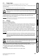
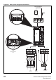
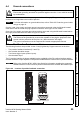
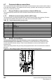
4.5.1 Position feedback connection details
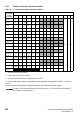
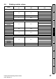
Table 4-1 P1 position feedback connection details
*
1
- One sine wave per revolution
*
2
- One cosine wave per revolution
*
3
- Freeze inputs are shown in the table above as ‘Frz’.
*
4
- The encoder power supply is selectable through parameter configuration to 5 Vdc, 8 Vdc and
15 Vdc.
Greyed cells are for P2 position feedback connections or simulated encoder outputs.
P1 Position
feedback
interface
Pr 03.038
Connections
123456789101112131415
AB (0) A A\ B B\ Z Z\
+V
*4
0 V Th
FD (1) F F\ D D\ Z Z\
FR (2) F F\ R R\ Z Z\
AB Servo (3) A A\ B B\ Z Z\ U U\ V V\ W W\
FD Servo (4) F F\ D D\ Z Z\ U U\ V V\ W W\
FR Servo (5) F F\ R R\ Z Z\ U U\ V V\ W W\
SC (6)
A
(Cos)
A\
(Cos\)
B
(Sin)
B\
(Sin\)
ZZ\
SC
Hiperface (7)
Cos Cosref Sin Sinref DATA DATA\
EnDat (8) DATA DATA\ CLK CLK\
Frz*
3
Frz\*
3
SC EnDat (9) A A\ B B\ DATA DATA\ CLK CLK\
SSI (10) DATA DATA\ CLK CLK\
Frz*
3
Frz\*
3
SC SSI (11)
A
(Cos)
A\
(Cos\)
B
(Sin)
B\
(Sin\)
DATA DATA\ CLK CLK\
SC Servo
(12)
A
(Cos)
A\
(Cos\)
B
(Sin)
B\
(Sin\)
ZZ\UU\VV\WW\
BiSS (13) DATA DATA\ CLK CLK\
Frz*
3
Frz*
3
Resolver (14) Cos H Cos L Sin H Sin L Ref H Ref L
SC SC (15)
A
(Cos)
A\
(Cos\)
B
(Sin)
B\
(Sin\)
ZZ\
C*
1
C\*
1
D*
2
D\*
2
Frz2*
3
Frz2\*
3
Commutation
Only (16)
UU\VV\ W W\
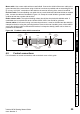
Frz and Frz\ on terminals 5 and 6 are for Freeze input 1. Frz2 and Frz2\ on terminals 11
and 12 are for Freeze input 2.
NOTE