Getting Started Guide Unidrive M700 Unidrive M701 Part Number: 0478-0001-05 Issue: 5 www.controltechniques.
For the purposes of compliance with the EC Machinery Directive 2006/42/EC: General Information This guide covers the basic information that is required to set-up and run the drive, in applications where a drive malfunction does not result in a mechanical hazard. When the drive is used in a safety related application, i.e. where a malfunction might result in a hazard, it is essential to refer to the full user guide. The Unidrive M700 / M701 User Guide is available for download from www.controltechniques.
Contents 1 2 Safety information .......................................................................................4 Product information ....................................................................................7 3 Mechanical installation .............................................................................14 4 Electrical installation .................................................................................20 5 Getting started ............................................
1 Safety information 1.1 Warnings, Cautions and Notes A Warning contains information which is essential for avoiding a safety hazard. WARNING A Caution contains information which is necessary for avoiding a risk of damage to the product or other equipment. CAUTION NOTE 1.2 A Note contains information, which helps to ensure correct operation of the product. Electrical safety - general warning The voltages used in the drive can cause severe electrical shock and/or burns, and could be lethal.
Access Drive access must be restricted to authorized personnel only. Safety regulations which apply at the place of use must be complied with. 1.6 Fire protection 1.7 Compliance with regulations This guide contains instruction for achieving compliance with specific EMC standards. Within the European Union, all machinery in which this product is used must comply with the following directives: 1.8 Electrical installation 2006/42/EC: Safety of machinery. 2004/108/EC: Electromagnetic Compatibility.
1.11 Electrical installation 1.11.1 Electric shock risk The voltages present in the following locations can cause severe electric shock and may be lethal: • AC supply cables and connections • Output cables and connections • Many internal parts of the drive, and external option units Unless otherwise indicated, control terminals are single insulated and must not be touched. 1.11.
Product information This guide covers the Unidrive M700 and the Unidrive M701 products. The Unidrive M700 product offers Ethernet fieldbus communications and the Unidrive M701 offers a 2 wire 485 serial interface. All other features of these two products are exactly the same.
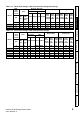
2.3 WARNING NOTE Table 2-1 Ratings Fuses The AC supply to the drive must be installed with suitable protection against overload and short-circuits. The following section shows recommended fuse ratings. Failure to observe this requirement will cause risk of fire. Nominal cables sizes below are provided as a guide only. Ensure cables used suit local wiring regulations. 200 V drive ratings, cable sizes and fuse ratings Max. cont.
Max. cont. input current Model 06400350 06400420 06400470 Heavy Duty Nom Motor Max. Nom Motor Max. Ferraz cont. power power cont. power power HSJ Input Output Input Output output IEC @ @ @ output @ gR Bussman current 400V 460V current 400V 460V DFJ A A A 36.5 46.2 60.6 63 63 63 40 50 70 mm2 10 16 25 mm2 AWG AWG 10 6 6 16 4 4 25 3 3 A kW hp A kW hp 38.0 48.0 63.0 18.5 22.0 30.0 25.0 30.0 40.0 35.0 42.0 47.0 15.0 18.5 22.0 25.0 30.0 30.
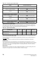
Table 2-5 Protective ground cable ratings Model Ground conductor size 03200050, 03200066, 03200080, 03200106, 04200137, 04200185, 06200330 Either use 10 mm2 cable or 2 cables of the same cross sectional area as the recommended phase cables 06200440 Either use 16 mm2 cable or 2 cables of the same cross sectional area as the recommended phase cables 03400025, 03400031, 03400045, 03400062, 03400078, 03400100, 04400150, 04400172, 06400420 Either use 10 mm2 cable or 2 cables of the same cross sectional a
Drive features Figure 2-3 Safety information 2.4 Features of the drive Product information Mechanical installation Electrical installation 1. Keypad connection 7. Option module slot 3 13. Braking terminal 2. Rating label 8. Relay connections 14. Internal EMC filter Getting started Key 9. Position feedback connections 15. DC bus + 4. Status LED 10. Control connections 16. DC bus - 5. Option module slot 1 11. Communications port 17. AC supply / motor connections 6.
2.5 Options / Accessories Figure 2-4 Drive features and options 1. Keypad 4. Option module slot 3 2. Option module slot 1 5. CT Comms cable 3. Option module slot 2 6. Internal braking resistor Table 2-7 7.
Parts supplied with the drive Description Size 3 Size 4 Safety information Table 2-9 Size 6 Control connectors x1 Product information x1 Relay connector x1 24 V power supply connector Mechanical installation x1 Electrical installation Grounding bracket x1 Surface mounting brackets x2 Getting started x2 x2 Grounding clamp Basic parameters x1 x1 DC terminal cover grommets Running the motor x2 M6 Nuts x 11 NV Media Card Operation M4 x 10 Taptite screws x2 Supply and motor connector
3 Mechanical installation 3.1 Safety information WARNING WARNING Follow the instructions The mechanical and electrical installation instructions must be adhered to. Any questions or doubt should be referred to the supplier of the equipment.
C B Product information Mechanical installation Electrical installation Getting started Basic parameters 200 7.87 227 8.94 Running the motor in 14.37 NV Media Card Operation Further information 15 Unidrive M700 Getting Started Guide Issue Number: 5 mm 365 C B A in 3.27 4.88 8.27 mm 83 124 210 in 3 4 6 Drive dimensions Figure 3-1 mm Size Safety information Drive dimensions 3.
3.5 Surface mounting Figure 3-2 Surface mounting dimensions (size 3, 4 and 6) 6.0 mm (0.24 in) 73.0 mm (2.87 in) Æ 5.5 mm (0.22 in) 106 mm (4.17 in) 53 mm 53 mm 8 mm (2.09 in) (0.32 in) (2.09 in) 370 mm (14.57 in) 3 375 mm (14.76 in) 4 196 mm (7.72 in) 7.0 mm (0.28 in) 6.0 mm (0.24 in) Æ 6.5 mm (0.26 in) x 4 holes 378 mm (14.88 in) 6 Æ7.0 mm (0.
Enclosure Enclosure Layout Please observe the clearances in the diagram below taking into account any appropriate notes for other devices / auxiliary equipment when planning the installation. Figure 3-3 Enclosure layout Locate Locateas as required required Product information Optional braking resistor and overload Locate optional braking resistor external to cubicle (preferably near to or on top of the cubicle).
3.7 EMC filters 3.7.1 Internal filter It is recommended that the internal EMC filter be kept in place unless there is a specific reason for removing it. If the drive is part of a regen system or it is connected to an IT supply then the internal EMC filter must be removed. The internal EMC filter reduces radio-frequency emission into the line power supply.
Removal of size 4 internal EMC filter Safety information Figure 3-5 Product information Mechanical installation Electrical installation To electrically disconnect the Internal EMC filter, remove the screw (1) as highlighted above. Figure 3-6 Removal of size 6 internal EMC filter Getting started Basic parameters Running the motor 1 To electrically disconnect the Internal EMC filter, remove the screw (1) as highlighted above.
4 Electrical installation WARNING WARNING WARNING WARNING WARNING WARNING WARNING 20 Electric shock risk The voltages present in the following locations can cause severe electric shock and may be lethal: AC supply cables and connections DC and brake cables, and connections Output cables and connections Many internal parts of the drive, and external option units Unless otherwise indicated, control terminals are single insulated and must not be touched.
Supply types All drives are suitable for use on any supply type i.e TN-S, TN-C-S, TT and IT. Supplies with voltage up to 600 V may have grounding at any potential, i.e. neutral, centre or corner (“grounded delta”) Supplies with voltage above 600 V may not have corner grounding NOTE Ratings A fuse or other protection must be included in all live connections to the AC supply.
4.
Size 4 power and ground connections Safety information Figure 4-2 DC / Brake connections Thermal overload protection device Product information Optional braking resistor +DC BR -DC Mechanical installation Additional ground connection Electrical installation Getting started 4 PE L1 L2 L3 U Basic parameters 1 Ground connection studs AC Connections V W Running the motor Optional EMC filter Optional line reactor NV Media Card Operation Fuses Motor L2 Mains Supply Unidrive M700 Getti
Figure 4-3 Size 6 power and ground connections DC Connections (DC and braking) Thermal overload protection device DC - DC + Optional braking resistor BR 6 AC Connections L1 L2 L3 Motor Connections PE U V W Ground connection studs Optional EMC filter Optional line reactor Fuses Motor L1 L2 Mains Supply 24 L3 Supply Ground Optional ground connection Unidrive M700 Getting Started Guide Issue Number: 5
WARNING Ground connections Electrochemical corrosion of grounding terminals Ensure that grounding terminals are protected against corrosion i.e. as could be caused by condensation. NOTE For further information on ground cable sizes, refer to Table 2-5 Protective ground cable ratings on page 10. WARNING Position feedback connections The following functions are provided via the 15-way high density D-type connector on the drive: Two position feedback interfaces (P1 and P2). One encoder simulation output.
4.5.1 Table 4-1 P1 Position feedback interface Pr 03.
Braking resistor values Model Minimum resistance * Instantaneous power rating Continuous power rating Ω kW kW 43 3.5 29 5.3 5 30.3 74 8.3 58 10.6 18 35.5 18 50.7 200 V 03200050 Product information 03200066 03200080 03200106 06200330 06200440 Safety information 4.
4.7 Communications connections The Unidrive M700 product offers Ethernet fieldbus communications and the Unidrive M701 offers a 2 wire 485 serial interface. This enables the drive set-up, operation and monitoring to be carried out with a PC or controller if required. 4.7.1 Ethernet Fieldbus communications (Unidrive M700 only) The Unidrive M700 provides two RJ45 connections with an Ethernet switch for easy network creation. 4.7.
Cable Twisted pair shield Shield connection to 0V Cable shield Cable shield Control connections Getting started 4.9 Ground clamp on shield Electrical installation Connection at motor Connection at drive Mechanical installation Twisted pair shield Product information Shield connection to 0V Safety information Motor cable: Use a motor cable with an overall shield.
5 Getting started This chapter introduces the user interfaces, menu structure and security level of the drive. 5.1 Understanding the display The keypad can only be mounted on the drive. 5.1.1 SI-Keypad The SI-Keypad display consists of two rows of text. The upper row shows the drive status or the menu and parameter number currently being viewed. The lower row of the display line shows the parameter value or the specific trip type.
Keypad operation 5.2.
Figure 5-3 Mode examples Do not change parameter values without careful consideration; incorrect values may cause damage or a safety hazard. WARNING NOTE When changing the values of parameters, make a note of the new values in case they need to be entered again. NOTE For new parameter-values to apply after the AC supply to the drive is interrupted, new values must be saved. Refer to section 5.7 Saving parameters on page 34. 5.
Advanced menus The advanced menus consist of groups or parameters appropriate to a specific function or feature of the drive. Menus 0 to 41 can be viewed on the SI-Keypad.
5.6 Changing the operating mode Changing the operating mode returns all parameters to their default value, including the motor parameters. User security status (00.049) and User security code (00.034) are not affected by this procedure). Procedure Use the following procedure only if a different operating mode is required: 1. Ensure the drive is not enabled, i.e. terminal 31 is open or Pr 06.015 is OFF (0) 2. Enter either of the following values in Pr mm.
Restoring parameter defaults Restoring parameter defaults by this method saves the default values in the drives memory. User security status (00.049) and User security code (00.034) are not affected by this procedure). Procedure • • • Press the red reset button Toggle the reset digital input Carry out a drive reset through serial communications by setting Pr 10.038 to 100 Displaying parameters with non-default values only 5.
6 Basic parameters (Menu 0) Parameter 00.001 Minimum Reference Clamp 00.002 Maximum Reference Clamp Range OL Default RFC-A RFC-S OL RFC-A RFC-S Type1 ±VM_NEGATIVE_REF_CLAMP1 Hz / rpm 0.0 Hz ±VM_POSITIVE_REF_CLAMP Hz / rpm 50Hz default: 50.0 Hz 60Hz default: 60.0 Hz 50Hz default: 1500.0 Hz 60Hz default: 1800.0 Hz 3000.0 rpm RW 0.0 rpm RW 00.003 Acceleration Rate 1 ±VM_ACCEL_R ATE s /100 Hz ±VM_ACCEL_RATE s /1000 rpm 5.0 s/100 Hz 2.000 s/1000 rpm 0.200 s/1000 RW 00.
00.021 Analog Input 3 Mode Range OL RFC-S OL RFC-A RFC-S Type1 Volt (6) RW Off (0) or On (1) OFF(0) RW 0.0 RW 0.0 to 400.0 Hz 0.0 to 4000.0 rpm 00.024 Preset Reference 1 ±VM_SPEED_FREQ_REF rpm 0.0 RW 00.025 Preset Reference 2 ±VM_SPEED_FREQ_REF rpm 0.0 RW 00.026 Preset Reference 3 ±VM_SPEED_ FREQ_REF Hz 0.0 Overspeed Threshold Preset Reference 4 ±VM_SPEED_ FREQ_REF Hz RW 1 to 100000 1024 0 to 2 NV Media Card Data Previously Loaded RW 0.
Range Parameter Rated Speed 00.045 OL RFC-A 0 to 180000 rpm 0.00 to 50000.00 rpm Motor Thermal Time Constant 1 00.046 Rated Current 00.047 Rated Frequency 00.048 Drive Mode 00.049 User Security Status 00.050 Software Version 00.051 Action On Trip Detection 00.052 Reset Serial Communications* Default RFC-S OL RFC-A 50Hz default: 1500 rpm 60Hz default: 1800rpm 50Hz default: 1450 rpm 60Hz default: 1750rpm 1.0 to 3000.0 s ±VM_RATED_CURRENT 0.0 to 3000.0 Hz 0.0 to 1667.
Parameter descriptions 6.1.1 Pr mm.000 Safety information 6.1 Product information Pr mm.000 is available in all menus, commonly used functions are provided as text strings in Pr mm.000 shown in Table 6-1. The functions in Table 6-1 can also be selected by entering the appropriate numeric values (as shown in Table 6-2) in Pr mm.000. For example, enter 7001 in Pr mm.000 to erase the file in NV media card location 001. Table 6-1 Commonly used functions in Pr mm.
Value Action 8yyy* NV Media card: Compare the data in the drive with file xxx 9555* NV media card: Clear the warning suppression flag 9666* NV media card: Clear the warning suppression flag 9777* NV media card: Clear the read-only flag 9888* NV media card: Set the read-only flag 9999* NV media card: Erase and format the NV media card 110S0 Transfer electronic nameplate motor object parameters from the drive to an encoder connected to the drive or an option module.
Safety information Product information Mechanical installation Electrical installation Getting started Basic parameters Running the motor NV Media Card Operation Further information 41 Unidrive M700 Getting Started Guide Issue Number: 5
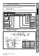
Figure 6-1 Menu 0 logic diagram 28 29 Analog reference 5 6 Analog Analog Input 2 Input 2 Offset Trim Destination 00.013 Analog Input 2 Mode 7 00.020 + + 00.019 Any unprotected variable parameter Analog ??.?? Reference 2 01.037 ??.?? 01.015 01.050 Pr 01.050 set >1 Bipolar Reference Select 00.024 Preset frequency reference 00.024 Preset Frequency 1 00.025 Preset Frequency 2 Open Loop only 00.026 00.027 Preset Frequency 3 Preset Frequency 4 Keypad reference A1.A2 0 A1.Preset 1 A2.
26 27 25 9 Safety information OL> FREQUENCY TORQUE RFC-A, RFC-S> SPEED RUN RUN FORWARD REVERSE RESET AT ZERO SPEED 10 24 Analog outputs Digital output Product information Mechanical installation Motor control Maximum Frequency/ SpeedClamp 00.006 Current Limit 00.014 Torque Mode Ramp Enable 00.002 Selector OL> Catch A Spinning Motor 00.033 RFC-A, RFC-S > Motor Full RFC-A, Load Rated Speed RFC-S> Autotune Current Demand 00.017 Filter Time Constant 000.16 00.
7 Running the motor This chapter takes the new user through all the essential steps to running a motor for the first time, in each of the possible operating modes. Ensure that no damage or safety hazard could arise from the motor starting unexpectedly. WARNING CAUTION CAUTION The values of the motor parameters affect the protection of the motor. The default values in the drive should not be relied upon. It is essential that the correct value is entered in Pr 00.046 Rated Current.
! Braking resistor (optional) 1 2 2 BR _ 3 0V Product information + +10V 4 Speed reference input 5 6 7 8 Communications port* Safety information Figure 7-1 Minimum connections to get the motor running in any operating mode (size 3 and 4) 9 10 AB AB Servo A A\ B B\ Z Z\ U U\ V V\ W W\ Cos Cosref Sin Sinref Data Data\ A (Cos) A\ (Cos\) B (Sin) B\ (Sin\) Data Data\ EnDat BiSS SSI Data Data\ CLK CLK\ Freeze Freeze T e r m i n a l Resolver 21 Cos H Cos L Sin H Sin L Ref H Ref L 22 34 2
Figure 7-2 Minimum connections to get the motor running in any operating mode (size 6) ! Braking resistor (optional) Size 6 only 1 2 2 3 _ 0V +10V 4 + BR Speed reference input 5 6 7 8 9 10 11 Communication ports* T e r m i n a l 21 22 24V 23 24 25 5 10 15 1 6 11 26 RUN FWD 27 RUN REV 28 29 Position feedback connector 15 way D-type 30 L1 L2 L3 U V W 31 SAFE TORQUE OFF (drive enable) Induction motor U V W Servo motor (permanent magnet) U V W E Keypad Optional item, must be insta
Quick Start / start-up 7.2.1 Open loop Detail Power-up the drive Verify that Open Loop mode is displayed as the drive powers up. If the mode is incorrect see section 5.6 Changing the operating mode on page 34. Ensure: • Drive displays ‘Inhibit’ Enter: • Motor rated frequency in Pr 00.047 (Hz) • Motor rated current in Pr 00.046 (A) • Motor rated speed in Pr 00.045 (rpm) Motor rated voltage in Pr 00.
Action Detail The drive is able to perform either a stationary or a rotating autotune. The motor must be at a standstill before an auto-tune is enabled. A rotating auto-tune should be used whenever possible so the measured value of power factor of the motor is used by the drive WARNING • Autotune • A rotating auto-tune will cause the motor to accelerate up to 2/3 base speed in the direction selected regardless of the reference provided. Once complete the motor will coast to a stop.
RFC-A mode (with position feedback) Induction motor with position feedback For simplicity only an incremental quadrature encoder will be considered here. For information on setting up one of the other supported speed feedback devices, refer to Setting up a feedback device in the Unidrive M700 / M701 User Guide.
Action Set acceleration / deceleration rates Detail Enter: • Acceleration rate in Pr 00.003 (s/1000 rpm) • Deceleration rate in Pr 00.004 (s/1000 rpm) (If braking resistor installed, set Pr 00.015 = FAST. Also ensure Pr 10.030, Pr 10.031 and Pr 10.061 are set correctly, otherwise premature ‘Brake R Too Hot’ trips may be seen). 1000rpm 0.03 0.04 t The drive is able to perform either a stationary or a rotating auto-tune. The motor must be at a standstill before an auto-tune is enabled.
RFC-S mode (with position feedback) Safety information 7.2.3 Permanent magnet motor with a position feedback For simplicity only an incremental quadrature encoder with commutation outputs will be considered here. For information on setting up one of the other supported speed feedback devices, refer to Setting up a feedback device in the Unidrive M700 / M701 User Guide.
Action Detail Enter: Set • Acceleration rate in Pr 00.003 (s/1000 rpm) acceleration / • Deceleration rate in Pr 00.004 (s/1000 rpm) (If braking resistor deceleration installed, set Pr 00.015 = Fast. Also ensure Pr 10.030, Pr 10.031 and rates Pr 10.061 are set correctly, otherwise premature ‘Brake R Too Hot’ trips may be seen). 1000rpm 0.03 t 0.04 The drive is able to perform either a stationary or a rotating auto-tune. The motor must be at a standstill before an auto-tune is enabled.
Save parameters 0 Select 'Save Parameters' in Pr mm.000 (alternatively enter a value of 1000 in Pr mm.000) and press red reset digital input. reset button or toggle the Mechanical installation Run 0 Product information Autotune (cont) Detail To perform an auto-tune: • Set Pr 00.040 = 1 for a stationary auto-tune, Pr 00.040 = 2 for a rotating auto-tune. • Close the run signal (terminal 26 or 27). • Close the drive enable signal (terminal 31).
8 NV Media Card Operation 8.1 Introduction The Non-Volatile Media Card feature enables simple configuration of parameters, parameter back-up and drive cloning using a SMARTCARD or SD card in the future. The drive offers backward compatibility for a Unidrive SP SMARTCARD. The SMARTCARD can be used for: • • Parameter copying between drives Saving drive parameter sets The NV Media Card (SMARTCARD) is located at the top of the module under the drive display (if installed) on the left-hand side.
SMARTCARD support Figure 8-2 Basic SMARTCARD operation Electrical installation Programs all drive parameters to the SMARTCARD Drive reads all parameters from the SMARTCARD NOTE Overwrites any data already in data block 1 Boot Auto Save Pr 00.030 = Auto + Pr 00.030 = Boot + Transferring data Data transfer, erasing and protecting the information is performed by entering a code in Pr mm.000 and then resetting the drive as shown in Table 8-1.
9 Further information 9.1 Diagnostics For further information on diagnostics including trips and alarms, refer to the Unidrive M700 / M701 User Guide.
1 11 Polarised signal connectors 41 42 21 31 1 0V 2 +24V input 3 0V 5 Non-inverting input 6 Inverting input 3 0V 5 Non-inverting input 6 Inverting input 4 +10V output 7 Analog input 2 Analog input 3 8 Analog input 3 9 Analog output 1 Speed / frequency 10 Analog output 2 11 0V 21 0V +24V output (user selectable) Analog frequency/speed reference 1 Single-ended signal Differential signal Analog frequency/speed reference 2 Torque (active current) 22 23 0V At zero spee