
User guide

92 Unidrive SP Short Form Guide
www.controltechniques.com Issue Number: 2
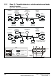
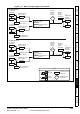
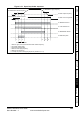
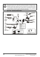
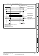
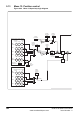
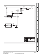
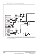
9.12 Menu 12: Threshold detectors, variable selectors and brake
control function
Figure 9-16 Menu 12 logic diagram
??.??
Any variable
parameter
??.??
12.03
Threshold
Detector 1
input source
12.04
Threshold
Detector 1
threshold level
Threshold
Detector 1
Threshold
Detector 1
x(-1)
12.06
Threshold
Detector 1
output invert
12.01
Threshold
Detector 1
output indicator
12.05
Threshold
Detector 1
hysteresis
??.??
Any
unprotected
bit parameter
??.??
12.07
Threshold
Detector
output
destination
parameter
1
??.??
Any variable
parameter
??.??
12.23
Threshold
Detector 2
input source
12.24
Threshold
Detector 2
threshold level
Threshold
Detector 2
Threshold
Detector 2
x(-1)
12.26
Threshold
Detector 2
output invert
12.02
Threshold
Detector 2
output indicator
12.25
Threshold
Detector 2
hysteresis
??.??
??.??
12.27
Threshold
Detector
output
destination
parameter
2
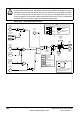
All
parameters
are shown
at their default setting
0.XX
0.XX
Key
Read-write
(RW)
parameter
Read-only (RO)
parameter
Input
terminals
Output
terminals
Hysteresis
Threshold
level
Threshold
output
t
t
Any
unprotected
bit parameter