
User guide

Unidrive SP Short Form Guide 85
Issue Number: 2 www.controltechniques.com
Safety
Information
Product
Information
Mechanical
Installation
Electrical
Installation
Getting Started Basic parameters
Running the
motor
SMARTCARD
Advanced
parameters
Diagnostics
UL Listing
Information
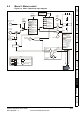
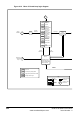
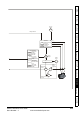
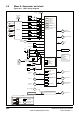
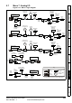
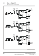
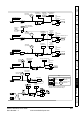
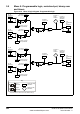
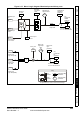
9.7 Menu 7: Analog I/O
Figure 9-12 Menu 7 logic diagram
Analog input 2
A/D
7.11
Analog input 2
mode selector
7.12
Analog
input 2
scaling
??.??
Any
unprotected
variable
parameter
??.??
7.14
7.25
Calibrate
analog input 1
full scale
7.26
V/f sample
time
7.07
Analog input
1 offset trim
7.08
Analog
input 1
scaling
??.??
Any
unprotected
variable
parameter
??.??
7.10
Analog input 1
destination
parameter
V/f
x(-1)
Analog input 1
Analog input 3
A/D
7.15
Analog input 3
mode selector
7.16
Analog
input 3
scaling
??.??
Any
unprotected
variable
parameter
??.??
7.18
??.??
Any variable
parameter
??.??
7.19
Analog output 1
source parameter
7.20
Analog
output
1
scaling
7.21
Analog
output
1
mode
selector
Analog output 1
??.??
Any
variable
parameter
??.??
7.22
Analog output 2
source parameter
7.23
Analog
output
2
scaling
7.24
Analog
output
2
mode
selector
7.09
Analog
input 1 invert
x(-1)
7.01
Analog
input 1
7.02
Analog
input 2
x(-1)
7.17
Analog
input 3
invert
7.13
Analog
input 2
invert
Analog output 2
1.36
Analog
ref. 1
1.37
Analog
ref. 2
5.01
Motor
frequency
3.02
Speed
feedback
4.02
Motor
active
current
OL>
CL>
0.XX
0.XX
Key
Read-write
(RW)
parameter
Read-only (RO)
parameter
Input
terminals
Output
terminals
The parameters are all shown at their default settings
+
+
+
+
7.30
Analog input
1 offset
7.28
Analog input 2
current loop loss
+
+
7.31
+
+
7.31
Analog input
2 offset
+
+
7.31
+
+
7.32
Analog input
3 offset
7.29
Analog input 3
current loop loss
7.33
Analog
output 1 control
Analog input 2
destination
parameter
Analog input 3
destination
parameter
7.03
Analog
input 3