
User guide

60 Unidrive SP Short Form Guide
www.controltechniques.com Issue Number: 2
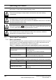
7.2.2 RFC mode
Induction motor
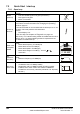
Action Detail
Before
power-up
Ensure:
• Drive Enable signal is not given (terminal 31)
• Run signal is not given
• Motor and feedback device are connected
Power-up
the drive
Verify that Closed Loop mode is displayed as the drive powers up. If
the mode is incorrect see section 5.6 Changing the operating
mode
on page 45.
If a motor thermistor is not connected and the drive trips on ‘th’ set
Pr 0.21 = VOLt and press the red reset button.
Ensure:
• Drive displays ‘inh’
If the drive trips, see Chapter 10 Diagnostics on page 107.
Size 0 only: If no internal braking resistor is installed then the drive will
trip ‘br.th’. If no internal braking resistor is required then set Pr 0.51 to 8
to disable the trip.
Select RFC
mode and
disable
encoder
wire-break
trip
•Set Pr 3.24 = 1 to select RFC mode
•Set Pr 3.40 = 0
Enter motor
nameplate
details
Enter:
• Motor rated frequency in Pr 0.47 (Hz)
• Motor rated current in Pr 0.46 (A)
• Motor rated speed (base speed - slip speed) in Pr 0.45 (rpm)
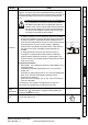
• Motor rated voltage in Pr 0.44 (V) - check if or connection
Set
maximum
speed
Enter:
• Maximum speed in Pr 0.02 (rpm)
Set
acceleration
/
deceleration
rates
Enter:
• Acceleration rate in Pr 0.03 (s/1000rpm)
• Deceleration rate in Pr 0.04 (s/1000rpm) (If braking resistor
installed, set Pr 0.15 = FAST. Also ensure Pr 10.30 and Pr 10.31
are set correctly, otherwise premature ‘It.br’ trips may be seen.)
Mot X XXXXXXXXX
No XXXXXXXXXX kg
IP55 I.cl F C 40 s S1
°
VHzmin
-1
kW cos
φ
A
230
400
50 1445 2.20 0.80 8.50
4.90
CN = 14.5Nm
240
415
50 1445 2.20 0. 76 8.50
4.90
CN = 14.4Nm
CTP- VEN 1PHASE 1=0,46A P=110W R.F 32MN
I.E.C 34 1(87)
0.02
t
1000rpm
0.03
t
0.04