
User guide

56 Unidrive SP Short Form Guide
www.controltechniques.com Issue Number: 2
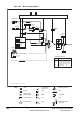
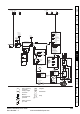
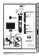
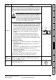
Figure 7-2 Minimum connections to get the motor running in any operating mode (size 1 to 3)
Closed loop vector
RFC
Open loop
UVW
A A
B B
U U
V V
W W
Z Z
1
UVW
A A
B B
Z Z
1
E E
Servo motor
(permanent
magnet)
Induction
motor
Servo
10
11
8
9
6
7
4
5
3
Speed
reference
input
RUN FWD
RUN REV
DRIVE
ENABLE
24V
0V
+10V
1
2
Marker pulse optional
Thermal overload for braking resistor
to protect against fire risk. This must be
wired to interrupt the AC supply in the
event of a fault. This is not required if the
optional internal braking resistor is used
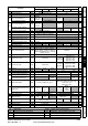
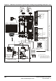
1 A F Cos
2 A\ F\ Cos\
3 B D Sin
4 B\ D\ Sin\
5 Z Data
6 Z\ Data\
7 U Fout Aout Fout Aout
8 U\ Fout\ Aout\ Fout\ Aout\
9 V Dout Bout Dout Bout
10 V\ Dout\ Bout\ Dout\ Bout\
11 W Clk
12 W\ Clk\
13 +V +V
14 0V 0V
15 Th Th
Terminal
Encoder connections
2
1
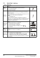
Pr
=PAd (4)
0.05
T
e
r
m
i
n
a
l
M
o
d
e
K
e
y
p
a
d
M
o
d
e
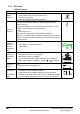
Serial
communications
port
Encoder connector
15 way D-type
5
10
15
1
6
11
SM-Keypad / SM-Keypad Plus.
Optional item, must be fitted
for keypad mode.
30
31
28
29
26
27
24
25
23
21
22
2
!
+
_
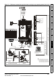
48V BR
Braking resistor
(optional) - Size 2
and 3 only
2
!
DC1 DC2 BR
DC1 = -
DC2 = +
Braking resistor
(optional) -
Size 1 only
L1
L2
L3
L1
L2
L3
U
VW
Fuses
PE