
User guide

40 Unidrive SP Short Form Guide
www.controltechniques.com Issue Number: 2
5 Getting Started
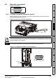
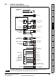
Figure 5-3 SP0 Keypad
This chapter introduces the user interfaces, menu structure and security level of the drive.
5.1 Understanding the display
There are two types of keypad available for the Unidrive SP. The SM-Keypad/SP0 Keypad has an
LED display and the SM-Keypad Plus has an LCD display.
Size 0: Only the SP0 Keypad can be installed to the drive.
Size 1 to 6: Both the SM-Keypad and SM-Keypad Plus can be installed to the drive.
For all sizes the SM-Keypad Plus can also be remotely mounted on an enclosure door.
5.1.1 SM-Keypad/SP0 Keypad (LED)
The display consists of two horizontal rows of 7
segment LED displays.
The upper display shows the drive status or the
current menu and parameter number being
viewed.
The lower display shows the parameter value or
the specific trip type.
5.1.2 SM-Keypad Plus (LCD)
The display consists of three lines of text.
The top line shows the drive status or the current
menu and parameter number being viewed on
the left, and the parameter value or the specific
trip type on the right.
The lower two lines show the parameter name or
the help text.
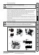
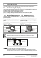
Figure 5-1 SM-Keypad Figure 5-2 SM-Keypad Plus
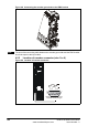
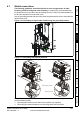
Beware of possible live terminals when attaching the SP0 Keypad to the drive.
Upper display
Lower display
Mode (black) button
Joypad
Fwd / Rev (blue) button
Stop/reset (red) button
Start (green) button
Control buttons
Mode (black) button
Joypad
Fwd / Rev (blue) button
Stop/reset (red) button
Start (green) button
Control buttons
Help button
WARNING
Mode (black) button
Stop/reset (red) button
Upper display
Lower display
Start (green) button
Fwd / Rev (blue) button
Navigation keys
The red stop button is also used to reset the drive.
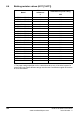
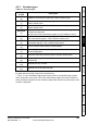
All keypads can indicate when a SMARTCARD access is taking place or when the
second motor map is active (menu 21). These are indicated on the displays as follows.
NOTE