
User guide

Unidrive SP Short Form Guide 39
Issue Number: 2 www.controltechniques.com
Safety
Information
Product
Information
Mechanical
Installation
Electrical
Installation
Getting Started Basic parameters
Running the
motor
SMARTCARD
Advanced
parameters
Diagnostics
UL Listing
Information
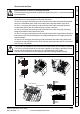
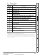
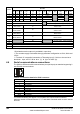
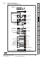
4.8 Control connections
Figure 4-13 Default terminal functions
*The SAFE TORQUE OFF / Drive enable terminal is a positive logic input only.
1
11
Polarised signal
connectors
21 31
41
42
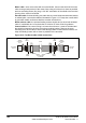
Analog frequency/speed
reference 1
Single-ended
signal
Differential signal
Analog input 2
Analog input 1
1
2
5
6
3
21
22
23
24
25
26
27
28
29
30
31
41
42
At zero speed
Reset
Run forward
Run reverse
Analog input 1/
input 2 select
Jog forward select
Drive ok
Speed / frequency
Analog
frequency/speed
reference 2
4
7
11
9
10
8
Torque (active
current)
Analog input 3
(Motor thermistor)
0V
+24V input
0V
Non-inverting input
Inverting input
0V
Non-inverting input
Inverting input
+10V output
Analog input 2
Analog input 3
Analog output 1
Analog output 2
0V
0V
+24V output
(user selectable)
0V
Digital I/O 1
Digital I/O 2
Digital I/O 3
Digital input 4
Digital input 5
Digital input 6
0V
Drive enable (SAFE
TORQUE OFF function)*
Relay (Overvoltage
category II)
Avoid connecting digital and analog grounds (T21 and T11).
NOTE