
User guide

36 Unidrive SP Short Form Guide
www.controltechniques.com Issue Number: 2
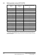
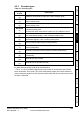
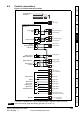
*Marker pulse is optional.
**Simulated encoder output only available in open-loop.
***The encoder supply is selectable through parameter configuration to 5Vdc, 8Vdc and
15Vdc.
****Terminal 15 is a parallel connection to T8 analog input 3. If this is to be used as a
thermistor input, set Pr 7.15 to ‘th.sc’ (7), ‘th’ (8) or ‘th.diSP’ (9).
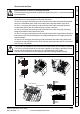
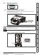
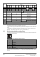
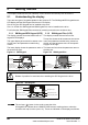
4.6 Serial communications connections
The Unidrive SP has a serial communications port (serial port) as standard supporting 2
wire EIA485 communications.
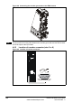
Table 4-2 Connection details for RJ45 connector
The communications port applies a 2 unit load to the communications network.
Minimum number of connections are 2, 3, 7 and shield. Shielded cable must be used at
all times.
Term
Pr 3.38
Ab
(0)
Fd
(1)
Fr
(2)
Ab.SErVO
(3)
Fd.SErVO
(4)
Fr.SErVO
(5)
SC
(6)
SC.HiPEr
(7)
EndAt
(8)
SC.EndAt
(9)
SSI
(10)
SC.SSI
(11)
1AFF A F F Cos
Cos Cos
2 A\ F\ F\ A\ F\ F\ Cosref Cosref Cosref
3BDR B D R Sin Sin Sin
4 B\ D\ R\ B\ D\ R\ Sinref Sinref Sinref
5Z*
Encoder input - Data (input/output)
6 Z\* Encoder input - Data\ (input/output)
7
Simulated encoder
Aout, Fout**
U
Simulated encoder
Aout, Fout**
8
Simulated encoder
Aout\, Fout\**
U\
Simulated encoder
Aout\, Fout\**
9
Simulated encoder
Bout, Dout**
V
Simulated encoder
Bout, Dout**
10
Simulated encoder
Bout\, Dout\**
V\
Simulated encoder
Bout\, Dout\**
11
W Encoder input - Clock (output)
12 W\ Encoder input - Clock\ (output)
13 +V***
14 0V common
15 th****
Pin Function
1120Ω Termination resistor
2RX TX
3 0V isolated
4 +24V (100 mA)
5 0V isolated
6 TX enable
7RX\ TX\
8 RX\ TX\ (if termination resistors are required, link to pin 1)
Shell 0V isolated
1
8