
User guide

Unidrive SP Short Form Guide 31
Issue Number: 2 www.controltechniques.com
Safety
Information
Product
Information
Mechanical
Installation
Electrical
Installation
Getting Started Basic parameters
Running the
motor
SMARTCARD
Advanced
parameters
Diagnostics
UL Listing
Information
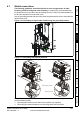
Ground connections
The drive must be connected to the system ground of the AC supply. The ground wiring
must conform to local regulations and codes of practice.
On size 0, the supply and motor ground connections are made using the M6 threaded
hole in the metal back plate of the drive located at the top and bottom of the drive.
On size 1, the supply and motor ground connections are made using the M5 studs
located either side of the drive near the plug-in power connector.
On size 2, the supply and motor ground connections are made using the grounding
bridge that locates at the bottom of the drive.
On size 3, the supply and motor ground connections are made using a M6 nut and bolt
that locates in the fork protruding from the heatsink between the AC supply and motor
output terminals.
On size 4 to 6, the supply and motor ground connections are made using M10 studs
located at the top and bottom of the drive near the input and output power connections.
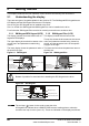
See Figure 4-4 for details.
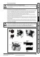
Figure 4-4 Ground connections
Electrochemical corrosion of earthing terminals
Ensure that grounding terminals are protected against corrosion i.e. as could be caused
by condensation.
WARNING
The ground loop impedance must conform to the requirements of local safety regulations.
The drive must be grounded by a connection capable of carrying the prospective fault
current until the protective device (fuse, etc.) disconnects the AC supply.
The ground connections must be inspected and tested at appropriate intervals.
WARNING
Supply
ground
Plain washers
Spring washer
M6 bolt
Motor
ground
Supply
ground
Motor
ground
0 1
2
3 4
5
6