
User guide

Unidrive SP Short Form Guide 29
Issue Number: 2 www.controltechniques.com
Safety
Information
Product
Information
Mechanical
Installation
Electrical
Installation
Getting Started Basic parameters
Running the
motor
SMARTCARD
Advanced
parameters
Diagnostics
UL Listing
Information
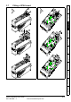
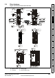
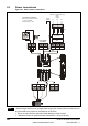
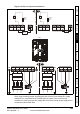
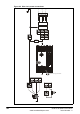
Figure 4-2 Size 1 to 3 power connections
On Unidrive SP size 2 and 3, the high current DC connections must always be used
when using a braking resistor, supplying the drive from DC (low voltage DC or high
voltage DC) or using the drive in a parallel DC bus system. The low current DC
connection is used to connect low voltage DC to the drive internal power supply and to
connect the internal EMC filter.
L1 L2
L2L1 L3 U V W
L3
PE
AC
BR48V -DC +DC
Internal
EMC filter
BRDC1
DC2
High current DC and braking
48V
-DC
+DC
Low current DC and 48V
DC1 = D 2 = +
-
C
DC
L1 L2
L2
L1
L3
UVW
L3
PE
Optional line reactor
Optional EMC filter
3 2 1
1 2 3
1 2 3
Optional
braking
resistor
Internal
EMC filter
Optional
braking
resistor
Optional EMC filter
Optional line reactor