
User guide

20 Unidrive SP Short Form Guide
www.controltechniques.com Issue Number: 2
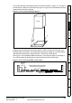
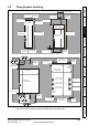
3.6 Enclosure
Enclosure Layout
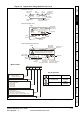
Please observe the clearances in the diagram below taking into account any
appropriate notes for other devices / auxiliary equipment when planning the installation.
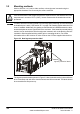
Figure 3-4 Enclosure layout
≥
100mm
(4in)
Enclosure
AC supply
contactor and
fuses or MCB
External
controller
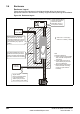
Signal cables
Plan for all signal cables
to be routed at least
300mm (12in) from the
drive and any power cable
Ensure minimum clearances
are maintained for the drive
and external EMC filter. Forced
or convection air-flow must not
be restricted by any object or
cabling
≥
100mm
(4in)
Optional braking resistor and overload
Locate optional braking
resistor and overload
external to cubicle
(preferably near to or
on top of the cubicle).
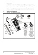
The external EMC filter can be
bookcase mounted (next to the
drive) or footprint mounted (with
the drive mounted onto the filter).
Note
For EMC compliance:
1) When using an external EMC
filter, one filter is required for
each drive
2) Power cabling must be at
least 100mm (4in) from the
drive in all directions
3) Ensure direct metal contact
at drive and filter mounting
points (any paint must be
removed)
A
A
Size 0 and 1: 0mm (0in)
Size 2 to 6: 30mm (1.181in)
≥
≥
A