
User guide

118 Unidrive SP Short Form Guide
www.controltechniques.com Issue Number: 2
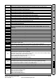
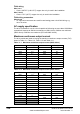
Status indications
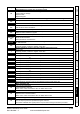
Table 10-3 Status indications
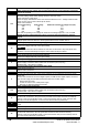
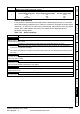
Table 10-4 Solutions Module and SMARTCARD status indications at power-up
Upper display Description Drive output
stage
ACt Regeneration mode active
Enabled
The regen unit is enabled and synchronised to the supply.
ACUU AC Supply loss
Enabled
The drive has detected that the AC supply has been lost and is attempting to maintain the DC
bus voltage by decelerating the motor.
dc DC applied to the motor
Enabled
The drive is applying DC injection braking.
dEC Decelerating
Enabled
The drive is decelerating the motor.
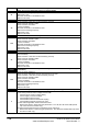
inh
Inhibit
Disabled
The drive is inhibited and cannot be run.
The drive enable signal is not applied to terminal 31 or Pr 6.15 is set to 0.
POS Positioning
Enabled
The drive is positioning/orientating the motor shaft.
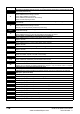
rdY Ready
Disabled
The drive is ready to be run.
run
Running
Enabled
The drive is running.
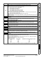
SCAn Scanning
Enabled
Regen> The drive is enabled and is synchronising to the line.
StoP Stop or holding zero speed
Enabled
The drive is holding zero speed.
Regen> The drive is enabled but the AC voltage is too low, or the DC bus voltage is still
rising or falling.
triP Trip condition
Disabled
The drive has tripped and is no longer controlling the motor. The trip code appears on the
upper display.
Lower display Description
boot
A parameter set is being transferred from the SMARTCARD to the drive during power-up.
cArd
The drive is writing a parameter set to the SMARTCARD during power-up.
loAding
The drive is writing information to a Solutions Module.