
User guide

114 Unidrive SP Short Form Guide
www.controltechniques.com Issue Number: 2
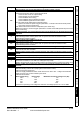
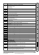
OV.P
Power module DC bus voltage has exceeded the peak level or the maximum continuous
level for 15 seconds
106
Increase deceleration ramp (Pr 0.04)
Decrease braking resistor value (staying above the minimum value)
Check nominal AC supply level
Check for supply disturbances which could cause the DC bus to rise – voltage overshoot after
supply recovery from a notch induced by DC drives.
Check motor insulation
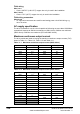
Drive voltage rating Peak voltage Maximum continuous voltage level (15s)
200 415 410
400 830 815
575 990 970
690 1190 1175
If the drive is operating in low voltage DC mode the overvoltage trip level is 1.45 x Pr 6.46.
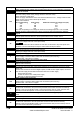
PAd
Keypad has been removed when the drive is receiving the speed reference from the
keypad
34
Fit keypad and reset
Change speed reference selector to select speed reference from another source
PH AC voltage input phase loss or large supply imbalance detected
32
Ensure all three phases are present and balanced
Check input voltage levels are correct (at full load)
N
Load level must be between 50 and 100% for the drive to trip under phase loss
conditions. The drive will attempt to stop the motor before this trip is initiated.
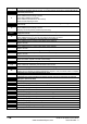
PH.P Power module phase loss detection
107
Ensure all three phases are present and balanced
Check input voltage levels are correct (at full load)
PS Internal power supply fault
5
Remove any Solutions Modules and reset
Check integrity of interface ribbon cables and connections (size 4,5,6 only)
Hardware fault - return drive to supplier
PS.10V 10V user power supply current greater than 10mA
8
Check wiring to terminal 4
Reduce load on terminal 4
PS.24V 24V internal power supply overload
9
The total user load of the drive and Solutions Modules has exceeded the internal 24V power
supply limit.
The user load consists of the drive’s digital outputs, the SM-I/O Plus digital outputs, the drive’s
main encoder supply and the SM-Universal Encoder Plus encoder supply.
• Reduce load and reset
• Provide an external 24V >50W power supply
• Remove any Solutions Modules and reset
PS.P Power module power supply fail
108
Remove any Solutions Modules and reset
Check integrity of interface ribbon cables and connections (size 4,5,6 only)
Hardware fault - return drive to supplier
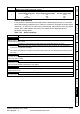
PSAVE.Er Power down save parameters in the EEPROM are corrupt
37
Indicates that the power was removed when power down save parameters were being saved.
The drive will revert back to the power down parameter set that was last saved successfully.
Perform a user save (Pr xx.00 to 1000 or 1001 and reset the drive) or power down the drive
normally to ensure this trip does or occur the next time the drive is powered up.
rS
Failure to measure resistance during autotune or when starting in open loop vector mode
0 or 3
33 Check motor power connection continuity
SAVE.Er User save parameters in the EEPROM are corrupt
36
Indicates that the power was removed when user parameters were being saved.
The drive will revert back to the user parameter set that was last saved successfully.
Perform a user save (Pr xx.00 to 1000 or 1001 and reset the drive) to ensure this trip does or
occur the next time the drive is powered up.
Trip Diagnosis
NOTE