
User guide

Unidrive SP Short Form Guide 113
Issue Number: 2 www.controltechniques.com
Safety
Information
Product
Information
Mechanical
Installation
Electrical
Installation
Getting Started Basic parameters
Running the
motor
SMARTCARD
Advanced
parameters
Diagnostics
UL Listing
Information
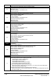
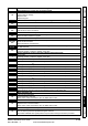
OIAC.P Power module over current detected from the module output currents
104
Acceleration /deceleration rate is too short.
If seen during autotune reduce voltage boost Pr 5.15
Check for short circuit on output cabling
Check integrity of motor insulation
Check feedback device wiring
Check feedback device mechanical coupling
Check feedback signals are free from noise
Is motor cable length within limits for that frame size?
Reduce the values in speed loop gain parameters – Pr 3.10, Pr 3.11 and Pr 3.12 (closed
loop vector and servo modes only)
Has offset measurement test been completed? (servo mode only)
Reduce the values in current loop gain parameters - Pr 4.13 and Pr 4.14 (closed loop vector and
servo modes only)
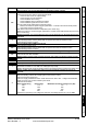
OI.br
Braking transistor over-current detected: short circuit protection for the braking transistor
activated
4
Check braking resistor wiring
Check braking resistor value is greater than or equal to the minimum resistance value
Check braking resistor insulation
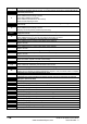
OIbr.P Power module braking IGBT over current
103
Check braking resistor wiring
Check braking resistor value is greater than or equal to the minimum resistance value
Check braking resistor insulation
OIdC.P Power module over current detected from IGBT on state voltage monitoring
109
Vce IGBT protection activated.
Check motor and cable insulation.
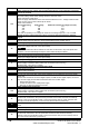
O.Ld1
Digital output overload: total current drawn from 24V supply and digital outputs exceeds
200mA
26 Check total load on digital outputs (terminals 24,25,26)and +24V rail (terminal 22)
O.SPd Motor speed has exceeded the over speed threshold
7
Increase the over speed trip threshold in Pr 3.08 (closed loop modes only)
Speed has exceeded 1.2 x Pr 1.06 or Pr 1.07 (open loop mode)
Reduce the speed loop P gain (Pr 3.10) to reduce the speed overshoot (closed loop modes only)
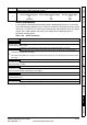
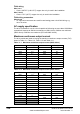
OV
DC bus voltage has exceeded the peak level or the maximum continuous level for 15
seconds
2
Increase deceleration ramp (Pr 0.04)
Decrease braking resistor value (staying above the minimum value)
Check nominal AC supply level
Check for supply disturbances which could cause the DC bus to rise – voltage overshoot after
supply recovery from a notch induced by DC drives.
Check motor insulation
Drive voltage rating Peak voltage Maximum continuous voltage level (15s)
200 415 410
400 830 815
575 990 970
690 1190 1175
If the drive is operating in low voltage DC mode the overvoltage trip level is 1.45 x Pr 6.46.
Trip Diagnosis