
User guide

108 Unidrive SP Short Form Guide
www.controltechniques.com Issue Number: 2
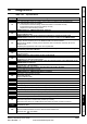
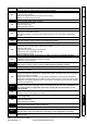
C.Prod
SMARTCARD trip: The data blocks on the SMARTCARD are not compatible with this
product
175
Erase all data on the SMARTCARD by setting Pr xx.00 to 9999 and pressing the red reset
button
Replace SMARTCARD
C.rdo SMARTCARD trip: SMARTCARD has the Read Only bit set
181
Enter 9777 in Pr xx.00 to allow SMARTCARD Read / Write access
Ensure card is not writing to data locations 500 to 999
C.rtg
SMARTCARD trip: The voltage and/or current rating of the source and destination drives
are different
186
Drive rating dependent parameters (parameters with the RA coding) are likely to have different
values and ranges with drives of different voltage and current ratings. Parameters with this
attribute will not be transferred to the destination drive by SMARTCARDs when the rating of the
destination drive is different from the source drive and the file is a parameter file. However, with
software V01.09.00 and later drive rating dependent parameters will be transferred if only the
current rating is different and the file is a differences from default type file.
Press the red reset button
Drive rating parameters are:
The above parameters will be set to their default values.
C.TyP SMARTCARD trip: SMARTCARD parameter set not compatible with drive
187
Press the reset button
Ensure destination drive type is the same as the source parameter file drive type
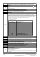
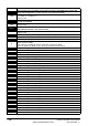
dESt Two or more parameters are writing to the same destination parameter
199 Set Pr xx.00 = 12001 check all visible parameters in the menus for duplication
EEF
EEPROM data corrupted - Drive mode becomes open loop and serial comms will timeout
with remote keypad on the drive RS485 comms port.
31 This trip can only be cleared by loading default parameters and saving parameters
Enc1 Drive encoder trip: Encoder power supply overload
189
Check encoder power supply wiring and encoder current requirement
Maximum current = 200mA @ 15V, or 300mA @ 8V and 5V
Enc2 Drive encoder trip: Wire break (Drive encoder terminals 1 & 2, 3 & 4, 5 & 6)
190
Check cable continuity
Check wiring of feedback signals is correct
Check encoder power is set correctly
Replace feedback device
If wire break detection on the main drive encoder input is not required, set Pr 3.40 = 0 to disable
the Enc2 trip
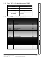
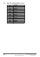
Trip Diagnosis
Parameter Function
2.08 Standard ramp voltage
4.05/6/7, 21.27/8/9 Current limits
4.24 User current maximum scaling
5.07, 21.07 Motor rated current
5.09, 21.09 Motor rated voltage
5.10, 21.10 Rated power factor
5.17, 21.12 Stator resistance
5.18 Switching frequency
5.23, 21.13 Voltage offset
5.24, 21.14 Transient inductance
5.25, 21.24 Stator inductance
6.06 DC injection braking current
6.48 Mains loss ride through detection level