Short Form Guide Unidrive SP Part Number: 0471-0162-02 Issue: 2 www.controltechniques.
General Information The manufacturer accepts no liability for any consequences resulting from inappropriate, negligent or incorrect installation or adjustment of the optional operating parameters of the equipment or from mismatching the variable speed drive with the motor. The contents of this guide are believed to be correct at the time of printing.
Contents 1 2 Safety Information ...................................................................................... 5 Product Information .................................................................................... 8 3 Mechanical Installation ............................................................................. 14 4 Electrical Installation ................................................................................ 26 5 Getting Started ..........................................
9 Advanced parameters ............................................................................... 69 10 11 Diagnostics .............................................................................................. 107 UL Listing Information ............................................................................ 119 9.1 9.2 9.3 9.4 9.5 9.6 9.7 9.8 9.9 9.10 9.11 9.12 9.13 9.14 9.15 9.16 9.17 9.18 Menu 1: Frequency / speed reference ................................................................
Safety Information Safety Information 1 Warnings, Cautions and Notes Product Information A Warning contains information which is essential for avoiding a safety hazard. WARNING CAUTION A Note contains information, which helps to ensure correct operation of the product. Electrical Installation NOTE Electrical safety - general warning Specific warnings are given at the relevant places in this User Guide.
The SAFE TORQUE OFF function has been approved by BGIA as meeting the requirements of the following standards, for the prevention of unexpected starting of the drive: EN 61800-5-2:2007 SIL 3 EN ISO 13849-1:2006 PL e EN 954-1:1997 Category 3 The SAFE TORQUE OFF function may be used in a safety-related application. The system designer is responsible for ensuring that the complete system is safe and designed correctly according to the relevant safety standards.
Adjusting parameters Electrical installation The voltages present in the following locations can cause severe electric shock and may be lethal: Stored charge The drive contains capacitors that remain charged to a potentially lethal voltage after the AC supply has been disconnected. If the drive has been energized, the AC supply must be isolated at least ten minutes before work may continue.
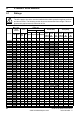
2 Product Information 2.1 Ratings WARNING Fuses The AC supply to the drive must be installed with suitable protection against overload and short-circuits. The following section shows recommended fuse ratings. Failure to observe this requirement will cause risk of fire. Table 2-1 Max. cont.
Table 2-2 3ph Fuse option 2 semi. fuse in series with HRC fuse or breaker Cable size EN60204 Normal Duty UL508C Heavy Duty HRC IEC North Max. Nom Motor Max. Nom Motor class IEC IEC America cont. power power cont.
Table 2-4 Size 6 Operating mode CL from cold CL from 100% OL from cold OL from 100% Normal Duty overload with motor rated current = drive rated current 110% for 165s 110% for 9s 110% for 165s 110% for 9s Heavy Duty overload with motor rated current = drive rated current 150% for 60s 150% for 8s 129% for 97s 129% for 15s Generally the drive rated current is higher than the matching motor rated current allowing a higher level of overload than the default setting as illustrated by the example of
Figure 2-2 Typical drive rating labels for size 1 to 6 Safety Information Rating label (size 1 to 6) Input voltage rating I/P 200-240V 50-60Hz SP1201 3ph Typical input current for Normal Duty rating 7.1A S.No: 3000005001 4.3 / 5.2A SP 1,5 TL Product Information Model No.
Output current The continuous output current ratings given on the rating label are for maximum 40°C (104°F), 1000m altitude and 3.0 kHz switching. Derating is required for higher switching frequencies, ambient temperatures >40°C (104°F) and higher altitude. For derating information, refer to the Unidrive SP User Guide on the CD supplied with the drive. Input current The input current is affected by the supply voltage and impedance.
Table 2-5 Parts supplied with the drive Size 0 Size 1 Size 2 Size 3 Size 4 Size 5 Size 6 Control connectors UL warning label Product Information Relay connector CAUTION Risk of Electric Shock Power down unit 10minutes before removing cover Mechanical Installation Grounding bracket Through panel mounting gasket Electrical Installation Through panel mounting bracket Getting Started Basic parameters Surface mounting brackets Top surface mounting brackets Nylon washers M6 M6 M8 M6 Sealing
3 Mechanical Installation Safety information WARNING WARNING Follow the instructions The mechanical and electrical installation instructions must be adhered to. Any questions or doubt should be referred to the supplier of the equipment.
Figure 3-1 Fire enclosure bottom layout Safety Information The location and size of the bottom shall cover the area shown in Figure 3-1. Any part of the side which is within the area traced out by the 5° angle is also considered to be part of the bottom of the fire enclosure.
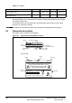
3.2 Mounting methods Unidrive SP size 1 to 6 can be either surface or through-panel mounted using the appropriate brackets. Size 0 can only be surface mounted. WARNING NOTE If the drive has been used at high load levels for a period of time, the heatsink can reach temperatures in excess of 70°C (158°F). Human contact with the heatsink should be prevented. In order to achieve IP54 rating (NEMA 12) for through-panel mounting, an IP54 insert must be installed (size 1 and 2). See section 10.7 on page 109.
Drive dimensions B Safety Information 3.3 C Product Information Mechanical Installation A Electrical Installation B in 12.677 14.488 14.488 14.488 20.079 32.283 44.528 mm 62 100 155 250 310 310 310 C in 2.441 3.937 6.102 9.843 12.205 12.205 12.205 mm 226 219 219 260 298 298 298 in 8.898 8.622 8.622 10.236 11.732 11.732 11.
3.4 Surface mounting 7.5mm (0.295in) 40.0±5.0mm (1.575±0.197in) 47mm (1.850in) 106 ±1.0mm 4.173 ±0.039in ∅6.5mm (0.256in) ∅6.5mm (0.256in) 30.0mm (1.181in) 24.5mm (0.965in) 0 1 292mm (11.496in) ∅5.4mm (0.213in) 370.0±1.0mm (14.567±0.039in) 6mm (0.236in) 106±1.0mm (4.173±0.039in) 2 ∅6.5mm (0.256in) 337.5 ±1.0mm (13.287 ±0.039in) ∅6.5mm (0.256in) 258.6±0.5mm (10.181±0.020in) ∅6.5mm (0.256in) ∅8.5mm (0.335in) 25.7±0.5mm (1.012±0.020in) 97mm (3.819in) 47mm (1.850in) 3 327±1.0mm (12.874±0.
Through-panel mounting Safety Information 3.5 70 ±0.3mm (2.756 ±0.012in) 70.0±0.3mm (2.756±0.012in) 93.0±0.5mm (3.661±0.020in) 35.0 ±0.15mm (1.378 ±0.006in) (0.256in) ∅6.5mm (0.256in) Product Information 35.0±0.15mm (1.378±0.006in) ∅ 6.5mm 64.6± 0.5mm 15.6±0.5mm (2.543 ±0.020in) (0.614±0.020in) 148 ±0.5mm (5.827 ±0.020in) Mechanical Installation 368.0±1.0mm (14.488±0.039in) 343.0±0.5mm (13.504±0.020in) 368.0 ±1.0mm (14.488 ±0.039in) 294 ±0.5mm (11.575 ±0.020in) (0.256in) 9.3 ±0.5mm (0.
3.6 Enclosure Enclosure Layout Please observe the clearances in the diagram below taking into account any appropriate notes for other devices / auxiliary equipment when planning the installation. Figure 3-4 Enclosure layout Optional braking resistor and overload Locate optional braking resistor and overload external to cubicle (preferably near to or on top of the cubicle).
Fitting of IP54 insert 3 1 1 2 Safety Information 3.7 3 2 2 1 Product Information 1 Mechanical Installation 4 4 Electrical Installation 5 5 6 7 Getting Started Basic parameters Running the motor 8 6 9 SMARTCARD Advanced parameters 4. The IP54 insert can be found in the accessories box. Diagnostics 6. The gasket can be found in the accessories box. UL Listing Information Unidrive SP Short Form Guide Issue Number: 2 www.controltechniques.
3.8 3.8.1 EMC filters Internal filter It is recommended that the internal EMC filter be kept in place unless there is a specific reason for removing it. If the drive is part of a regen system or is a Unidrive SP size 3 to 6 on an IT supply then the internal EMC filter must be removed. The internal EMC filter reduces radio-frequency emission into the line power supply.
Figure 3-7 Removal of Size 4 to 6 internal EMC filters Safety Information 1 Product Information 2 Mechanical Installation Electrical Installation 3.8.2 External filter Epcos L1, L2, L3 No. Getting Started Basic parameters Schaffner No. L1, L2, L3 1 ph SP0201 SP0202 2 0.8 N m 4mm2 0.8 N m SP0203 4200-6000 4mm 12AWG (0.6 lb ft) 12AWG (0.6 lb ft) SP0204 SP0205 3 ph 0.8 N m 4mm2 0.8 N m 4mm2 12AWG (0.6 lb ft) 12AWG (0.6 lb ft) 4200-6002 0.8 N m 4mm2 0.8 N m 4mm2 12AWG (0.6 lb ft) 12AWG (0.
Schaffner No. SP2401 SP2402 SP2403 SP2404 SP3201 SP3202 SP3401 SP3402 SP3403 SP3501 SP3502 SP3503 SP3504 SP3505 SP3506 SP3507 SP4201 SP4202 SP4203 SP4401 SP4402 SP4403 SP4601 SP4602 SP4603 SP4604 SP4605 SP4606 SP5201 SP5202 SP5401 SP5402 SP5601 SP5602 SP6401 SP6402 SP6601 SP6602 Epcos L1, L2, L3 No. L1, L2, L3 4200-6210 10mm2 8AWG 2Nm (1.5 lb ft) M5 2 1.35 N m 3.5 N m 4200-6211 10mm (2.6 lb ft) 8AWG (1.0 lb ft) M5 3.0 N m (2.2 lb ft) 4200-6307 16mm2 6AWG 2.2 N m (1.6 lb ft) M6 2 3.
Drive features Safety Information 3.9 Figure 3-8 Features of the size 0 to 6 drive M6 4Nm M3.5 1Nm LED A SMARTCARD SM 2 1 LED A 0 8 Product Information SMARTCARD 1 B 8 SM 1 1-6 SM 2 2.5mm 4Nm 21 SM 1 11 31 3mm 4Nm 5 10 15 B 31 42 41 3mm 4Nm Electrical Installation 8mm 4Nm 8mm 4Nm M6 4Nm 2.5mm 4Nm 21 1 6 11 42 41 11 1 C Mechanical Installation SM 3 1 M3.5 1Nm DC DC Pozi Pz 2 / 6.5mm 1.5Nm T20 / 6.5mm 1.5Nm T20 / 6.5mm 1.5Nm D D 1 2 AC Pozi Pz 2 / 6.5mm 1.
4 Electrical Installation Electric shock risk The voltages present in the following locations can cause severe electric shock and may be lethal: WARNING WARNING WARNING WARNING WARNING WARNING WARNING 26 • AC supply cables and connections • DC and brake cables, and connections • Output cables and connections • Many internal parts of the drive, and external option units Unless otherwise indicated, control terminals are single insulated and must not be touched.
Supply types Safety Information 4.1 All drives are suitable for use on any supply type i.e TN-S, TN-C-S, TT and IT. Supplies with voltage up to 600V may have grounding at any potential, i.e. neutral, centre or corner (“grounded delta”) Drives are suitable for use on supplies of installation category III and lower, according to IEC60664-1.
4.3 Power connections Figure 4-1 Size 0 power connections SP020X = 200 to 240V±10% SP040X = 380 to 480V±10% Connectors specification: Maximum size of power cable = 4.
Figure 4-2 Size 1 to 3 power connections Safety Information 1 23 -DC +DC Optional braking resistor DC1 DC2 BR BR 48V -DC +DC DC1 = - DC2 = + Internal EMC filter High current DC and braking Mechanical Installation 48V Product Information Optional braking resistor Low current DC and 48V Internal EMC filter Electrical Installation DC 2 Getting Started Basic parameters 3 1 1 PE L1 L2 L3 U V W Running the motor AC 23 L1 L2 L3 PE U V W SMARTCARD Optional EMC filter Opti
Figure 4-3 Size 4 to 6 power connections L1 L2 L3 Optional line reactor Optional EMC filter L1 PE L2 L3 +DC -DC Internal EMC filter 456 6 U V W +DC 30 Heatsink fan supply connections BR www.controltechniques.
Ground connections 1 2 Running the motor 0 Getting Started Basic parameters Supply ground Electrical Installation Figure 4-4 Ground connections Mechanical Installation WARNING The ground loop impedance must conform to the requirements of local safety regulations. The drive must be grounded by a connection capable of carrying the prospective fault current until the protective device (fuse, etc.) disconnects the AC supply.
4.4 Braking resistor values (40°C [104°F]) Model Minimum resistance* Instantaneous power rating Ω kW SP0201 ~ SP0205 35 4.35 SP0401 ~ SP0405 105 5.79 SP1201 ~ SP1203 43 3.5 SP1204 29 5.3 SP1401 ~ SP1404 74 8.3 SP1405 ~ SP1406 58 10.6 SP2201 - SP2203 18 8.9 SP2401 ~ SP2404 19 33.1 SP3201 ~ SP3202 5.0 30.3 SP3401 ~ SP3403 18 35.5 SP3501 ~ SP3507 18 50.7 SP4201 ~ SP4203** 5.0 30.3 SP4401 ~ SP4402** 11 55.3 SP4403** 9 67.6 SP4601 ~ SP4606** 13 95.
Encoder connections Safety Information 4.5 Figure 4-5 Encoder 1 6 11 5 10 15 Product Information 4.5.1 Location of encoder connector (size 0) Mechanical Installation Before using the encoder connector on size 0 for the first time, the break-out need removing as shown in Figure 4-6. Figure 4-6 Access to encoder connections Running the motor NOTE After removing the break-out, ensure that the ground tab is connected to ground. This will connect 0V of the drive to ground.
Figure 4-8 Connecting the encoder ground tab to the EMC bracket NOTE The size of the connecting cable between the encoder ground tab and the EMC bracket should be equal to the input cable. 4.5.2 Location of encoder connector (size 1 to 6) Figure 4-9 Location of encoder connector 5 10 15 1 6 11 Drive encoder connector Female 15-way D-type 34 www.controltechniques.
Encoder types Safety Information 4.5.3 Table 4-1 Encoder types Setting of Pr 3.
Pr 3.38 Term Ab (0) Fd (1) Fr Ab.SErVO Fd.SErVO Fr.SErVO SC SC.HiPEr EndAt SC.EndAt SSI SC.
Shield connections Product Information The following guidelines should be followed to ensure suppression of radiofrequency emission and good noise immunity. It is particularly recommended that the guidelines for the encoder cable be followed closely in order to avoid disturbance to the encoder operation from electrical noise. Use the grounding bracket and grounding clamp supplied with the drive to terminate the shields at the drive.
Motor cable: use a motor cable with an overall shield. Connect the shield of the motor cable to the ground terminal of the motor frame using a link that is as short as possible and not exceeding 50mm (2in) long. A full 360° termination of the shield to the terminal housing of the motor is beneficial. Encoder cable: for best shielding use cable with an overall shield and individual shields on twisted pairs, connect the cable as illustrated in Figure 4-12.
Control connections Safety Information 4.
5 Getting Started This chapter introduces the user interfaces, menu structure and security level of the drive. 5.1 Understanding the display There are two types of keypad available for the Unidrive SP. The SM-Keypad/SP0 Keypad has an LED display and the SM-Keypad Plus has an LCD display. Size 0: Only the SP0 Keypad can be installed to the drive. Size 1 to 6: Both the SM-Keypad and SM-Keypad Plus can be installed to the drive.
SM-Keypad Plus Second motor map active The decimal point after the third digit in the upper display will flash. 5.2 Keypad operation Control buttons The display examples in this section show the SM-Keypad 7 segment LED display. The examples are the same for the SM-Keypad Plus except that the information displayed on the lower row on the SM-Keypad is displayed on the right hand side of the top row on the SM-Keypad Plus.
Figure 5-4 Display modes Status Mode (Display not flashing) To enter Parameter Mode, press key or Timeout** Timeout** To return to Status Mode, press key Parameter Mode (Upper display flashing) When returning to Parameter Mode use the * Use Temporary Parameter Mode (Upper display flashing) keys to select another parameter to change, if required * keys to select parameter for editing To exit Edit Mode, press key To enter Edit Mode, press key RO parameter Timeout** R/W parameter Edit Mode (Cha
Menu 0 Figure 5-6 Menu 0 copying Menu 2 Mechanical Installation 2.21 5 Menu 0 0.04 0.05 0.06 Menu 1 5 0 150 Electrical Installation 1.14 0 Menu 4 5.4 150 Menu structure The drive parameter structure consists of menus and parameters. The drive initially powers up so that only menu 0 can be viewed. The up and down arrow buttons are used to navigate between parameters and once level 2 access (L2) has been enabled (see Pr 0.49) the left and right buttons are used to navigate between menus.
5.5 Advanced menus The advanced menus consist of groups or parameters appropriate to a specific function or feature of the drive. Menus 0 to 22 can be viewed on both keypads. Menus 40 and 41 are specific to the SM-Keypad Plus (LCD). Menus 70 to 91 can be viewed with an SMKeypad Plus (LCD) only when an SM-Applications is installed.
SM-Keypad Plus set-up menus Menu 40 parameter descriptions Parameter Parameter 0 40.01 Language selection 40.04 40.06 40.07 LCD contrast Drive and attribute database upload was bypassed Browsing favourites control Keypad security code 40.08 Communication channel selection 40.09 40.10 40.11 40.19 40.20 40.21 40.22 Hardware key code Drive node ID (Address) Flash ROM memory size String database version number Screen saver strings and enable Screen saver interval Turbo browse time interval 40.
3. Change the setting of Pr 0.48 as follows: Pr 0.48 setting Operating mode 1 Open-loop 2 Closed-loop Vector 3 Closed-loop Servo 4 Regen (See the Unidrive SP Regen User Guide for more information about operating in this mode) The figures in the second column apply when serial communications are used. 4. • • • 5.7 Either: Press the red reset button Toggle the reset digital input Carry out a drive reset through serial communications by setting Pr 10.38 to 100 (ensure that Pr. xx.00 returns to 0).
Please note that this function can be affected by the access level enabled, refer to section 5.11 Parameter access level and security for further information regarding access level. Product Information 5.10 Displaying parameters with non-default values only By entering 12000 in Pr xx.00, the only parameters that will be visible to the user will be those containing a non-default value. This function does not require a drive reset to become active. In order to deactivate this function, return to Pr xx.
5.11.1 Access Level The access level is set in Pr 0.49 and allows or prevents access to the advanced menu parameters. L1 access selected - Menu 0 only visible Pr 0.00 Pr 0.01 Pr 0.02 Pr 0.03 Pr 1.00 Pr 1.01 Pr 1.02 Pr 1.03 Pr 0.49 Pr 0.50 Pr 1.49 Pr 1.50 ............ ............ ............ ............ ............ ............ ............ ............ Pr 19.00 Pr 19.01 Pr 19.02 Pr 19.03 Pr 20.00 Pr 20.01 Pr 20.02 Pr 20.03 Pr 19.49 Pr 19.50 Pr 20.49 Pr 20.
5.11.3 User Security User security open - All parameters: Read / Write access Safety Information The User Security, when set, prevents write access to any of the parameters (other than Pr. 0.49 and Pr 11.44 Access Level) in any menu. Product Information Pr 0.49 Pr 0.50 Pr 1.49 Pr 1.50 ............ ............ ............ ............ ............ ............ ............ ............ Pr 21.00 Pr 21.01 Pr 21.02 Pr 21.03 Pr 22.00 Pr 22.01 Pr 22.02 Pr 22.03 Pr 21.30 Pr 21.31 Pr 22.28 Pr 22.
6 Basic parameters (Menu 0) Range(Ú) Parameter OL 0.00 xx.00 {x.00} 0.01 Minimum reference clamp {1.07} 0.02 Maximum reference clamp 0.03 Acceleration rate 0.04 Deceleration rate {1.06} {2.11} {2.21} 0.05 Reference select {1.14} 0.06 Current limit {4.07} 0.07 0.08 0.09 0.10 OL> Voltage mode select {5.14} CL> Speed controller P gain {3.10} OL> Voltage boost {5.15} CL> Speed controller I gain {3.11} OL> Dynamic V/F {5.13} CL> Speed controller D gain {3.
Range(Ú) 0.23 Jog reference 0.24 Pre-set reference 1 0.25 Pre-set reference 2 {1.05} {1.21} {1.22} OL> Pre-set reference 3 {1.23} CL> Overspeed threshold {3.08} OL> Pre-set reference 4 {1.24} 0.27 0.30 Parameter copying 0.37 Serial comms address 0 RW 0 to 50,000 1024 0.40 Autotune 0.41 Maximum switching frequency 0.42 No. of motor poles OL & VT> Motor rated power factor 0.43 SV> Encoder phase angle {5.12} {5.18} {5.
Figure 6-1 Menu 0 logic diagram 28 29 The function of the two digital inputs are controlled by the setting of Pr 0.05 (reference selector). See table below for details. Analog reference 5 6 Analog input 2 offset trim 0.13 Analog input 2 mode Analog input 2 destination Any unprotected variable parameter 0.20 + ??.?? + 0.19 7 Analog reference 2 1.37 0.05 ??.?? Reference selector OR Bipolar reference select 0.22 Preset frequency reference 0.24 Preset frequency 1 0.
26 OL> FREQUENCY CL> SPEED RESET 27 25 TORQUE 9 Safety Information RUN RUN FORWARD REVERSE AT ZERO SPEED 10 24 Analog outputs Digital output Product Information Mechanical Installation Motor control 0.02 Ramp enable 0.06 Current limit 0.14 Torque mode selector 0.16 Minimum frequency/ speed clamp 0.33 0.01 0.
7 Running the motor This chapter takes the new user through all the essential steps to running a motor for the first time, in each of the possible operating modes. Ensure that no damage or safety hazard could arise from the motor starting unexpectedly. WARNING CAUTION CAUTION The values of the motor parameters affect the protection of the motor. The default values in the drive should not be relied upon. It is essential that the correct value is entered in Pr 0.46 Motor rated current.
Figure 7-1 Minimum connections to get the motor running in any operating mode (size 0) L2 Safety Information L3 L1 Product Information Fuses ! Braking resistor (optional) 2 Mechanical Installation 1 L1 L2 L3 2 3 0V +10V 4 Speed reference input 5 Electrical Installation 6 7 Serial communications port 8 9 T e r m i n a l 11 Encoder connections Terminal 1 2 3 4 5 6 7 8 9 10 11 12 13 14 15 A A\ B B\ U U\ V V\ F F\ D D\ Z Z\ Fout Fout\ Dout Dout\ W W\ +V 0V Th Aout Aout\ Bout Bout\ Cos
Figure 7-2 Minimum connections to get the motor running in any operating mode (size 1 to 3) ! Braking resistor (optional) - Size 2 and 3 only ! Braking resistor (optional) Size 1 only 2 2 1 DC1 = DC2 = + DC1 DC2 BR 48V _ + 2 BR 3 0V +10V 4 Speed reference input 5 6 7 Serial communications port 8 9 10 Encoder connections Terminal 1 2 3 4 5 6 7 8 9 10 11 12 13 14 15 A A\ B B\ U U\ V V\ Z Z\ Fout Fout\ Dout Dout\ W W\ +V 0V Th F F\ D D\ Aout Aout\ Bout Bout\ 5 10 15 21 22 24V 23 24 25
Figure 7-3 Minimum connections to get the motor running in any operating mode (size 4 to 6) L2 Safety Information L3 L1 Product Information Fuses 1 3 Mechanical Installation 2 L1 L2 L3 0V +10V 4 Speed reference input 5 6 Electrical Installation 7 Serial communications port 8 9 10 1 2 3 4 5 6 7 8 9 10 11 12 13 14 15 A A\ B B\ F F\ D D\ Z Z\ Fout Fout\ Dout Dout\ W W\ +V 0V Th U U\ V V\ Aout Aout\ Bout Bout\ Cos Cos\ Sin Sin\ Data Data\ Fout Aout Fout\ Aout\ Dout Bout Dout\ Bout\ Clk Clk\
7.2.1 Quick Start / start-up Open loop Action Detail Before power-up Ensure: • The drive enable signal is not given (terminal 31) • Run signal is not given • Motor is connected Power-up the drive Verify that Open Loop mode is displayed as the drive powers up. If the mode is incorrect see section 5.6 Changing the operating mode on page 45. If a motor thermistor is not connected and the drive trips on ‘th’ set Pr 0.21 = VOLt and press the red reset button.
Detail Safety Information Action WARNING cos ∅ Getting Started Basic parameters • A stationary autotune can be used when the motor is loaded and it is not possible to uncouple the load from the motor shaft. A stationary autotune measures the stator resistance of the motor and the voltage offset in the drive. These are required for good performance in vector control modes.
RFC mode Induction motor Action Before power-up Power-up the drive Select RFC mode and disable encoder wire-break trip Enter motor nameplate details Detail Ensure: • Drive Enable signal is not given (terminal 31) • Run signal is not given • Motor and feedback device are connected Verify that Closed Loop mode is displayed as the drive powers up. If the mode is incorrect see section 5.6 Changing the operating mode on page 45. If a motor thermistor is not connected and the drive trips on ‘th’ set Pr 0.
Detail Safety Information Action WARNING cos ∅ RS σLS LS T Nm saturation breakpoints N rpm To perform an autotune: • • SMARTCARD • Running the motor • Set Pr 0.40 = 1 for a stationary autotune or set Pr 0.40 = 2 for a rotating autotune Close the Drive Enable signal (terminal 31). The drive will display ‘rdY’ Close the run signal (terminal 26 or 27). The lower display will flash ‘Auto’ and ‘tunE’ alternatively, while the drive is performing the autotune.
7.2.3 Closed loop vector mode Induction motor with incremental encoder feedback For simplicity only an incremental quadrature encoder will be considered here. For information on setting up one of the other supported speed feedback devices, refer to Setting up a feedback device in the Unidrive SP User Guide on the CD Rom supplied with the drive.
Detail Safety Information Action WARNING cos ∅ RS σLS LS T Nm saturation breakpoints N rpm To perform an autotune: • • SMARTCARD • Running the motor • Set Pr 0.40 = 1 for a stationary autotune or set Pr 0.40 = 2 for a rotating autotune Close the Drive Enable signal (terminal 31). The drive will display ‘rdY’ Close the run signal (terminal 26 or 27). The lower display will flash ‘Auto’ and ‘tunE’ alternatively, while the drive is performing the autotune.
7.2.4 Servo Permanent magnet motor with a speed and position feedback device For simplicity only an incremental quadrature encoder with commutation outputs will be considered here.
Detail • The normal low speed test will rotate the motor by up to 2 revolutions in the direction selected, regardless of the reference provided. Once complete the motor will come to a standstill. The run signal must be removed before the drive can be made to run at the required reference. The drive can be stopped at any time by removing the run signal or removing the Drive Enable. The motor must be uncoupled from the load before attempting this autotune.
8 SMARTCARD 8.1 Introduction This is a standard feature that enables simple configuration of parameters in a variety of ways. The SMARTCARD can be used for: • Parameter copying between drives • Saving whole drive parameter sets • Saving ‘differences from default‘ parameter sets • Storing Onboard PLC programs • Automatically saving all user parameter changes for maintenance purposes • Loading complete motor map parameters Size 0 When inserting the SMARTCARD, always ensure that ST SP0 arrow points upwards.
Figure 8-1 Installation of the SMARTCARD Safety Information SMARTCARD installed + 0 0.3 + - Pr to Au Prog eter ram Pa + rEAd Installing the SMARTCARD bo ot + Product Information Mechanical Installation Electrical Installation Size 0: Ensure the SMARTCARD is inserted with the contacts facing the left-hand side of the drive. Size 1 to 6: Ensure the SMARTCARD is inserted with the contacts facing the right-hand side of the drive.
Table 8-1 SMARTCARD data blocks Data block Type Example use 1 to 499 Read/Write Application set-ups 500 to 999 Read only Macros Data transfer to or from the SMARTCARD is indicated by one the following: • • SM-Keypad: The decimal point after the fourth digit in the upper display will flash. SM-Keypad Plus: The symbol 'CC' will appear in the lower left hand corner of the display. The card should not be removed during data transfer, as the drive will produce a trip.
Advanced parameters Safety Information 9 Figure 9-1 shows the overall block diagram of the drive.
9.1 Menu 1: Frequency / speed reference Figure 9-2 Menu 1 logic diagram LOCAL/REMOTE Analog reference Analog input 1 Analog reference 1 Menu 8 1.36 Menu 7 1.41 Analog reference 2 select 1.42 Preset reference select 1.43 Keypad reference select 1.44 Precision reference select 1.37 Analog input 2 Analog reference 2 Preset reference Preset reference selector* 1.15 Preset reference select bits 1 ~ 3 1.47 1.46 1.45 Reference selector* 1.14 Reference selected indicator 1.49 1.21 ~ 1.
RUN FORWARD Product Information Sequencer (Menu 6) Reference in skip freq./speed band indicator 1.13 Menu 13 Position control 1.10 1.11 Reverse selected indicator 1.12 1.40 1.06 1.02 1.35 Pre-ramp reference Pre-filter reference 1.03 Maximum freq./speed "clamp" 1.07 1.08 Menu 2 Minimum freq./speed "clamp" (Maximum reverse freq.
9.2 Menu 2: Ramps Figure 9-3 Menu 2 logic diagram Acceleration rate select bits 2.34 Key 2.33 2.32 2.32 Input terminals 0.XX Read-write (RW) parameter 0 0 0 0 1 Output terminals 0.XX 0 Read-only (RO) parameter 0 1 0 0 1 1 1 0 0 1 0 1 1 1 0 1 1 1 The parameters are all shown at their default settings Acceleration rate selector 2.10 Acceleration rates 1 ~ 8 2.11 Acceleration rate 1 2.12 Acceleration rate 2 2.13 Acceleration rate 3 2.14 Acceleration rate 4 2.
Safety Information Deceleration rate select bits 2.37 2.36 2.35 Product Information Mechanical Installation Deceleration rate selector 2.20 Electrical Installation 2.29 Running the motor N Preset reference selected indicator Jog deceleration rate 1.13 Forward Decel. rate Getting Started Basic parameters 1.50 Jog selected indicator Reverse Decel. rate N t Current control Menu 4 (Open-loop only) Deceleration Ramp control S-Ramp enable** 2.07 S-Ramp acceleration limit 2.
9.3 Menu 3: Frequency slaving, speed feedback and speed control Figure 9-4 Menu 3 Open-loop logic diagram Drive encoder speed Drive encoder reference 3.27 15 way sub-D connector Drive encoder reference Any destination unprotected variable 3.46 parameter Maximum drive encoder reference 3.43 3.42 Drive encoder reference scaling 3.45 ??.?? 3.44 ??.?? Drive encoder filter Frequency slaving enable 3.13 Encoder A A B B 1 2 3 4 3.34 Drive encoder lines per revolution 3.
Safety Information Product Information Mechanical Installation Electrical Installation Getting Started Basic parameters Running the motor SMARTCARD Advanced parameters Diagnostics UL Listing Information 75 www.controltechniques.
Figure 9-5 Menu 3 Closed loop logic diagram Hard speed reference Hard speed reference selector Reference enabled indicator Post-ramp reference 3.22 3.23 1.11 Final speed reference + + 2.01 3.01 15 way sub-D connector Drive encoder filter ENCODER INTERFACE 3.38 A Encoder A B B Z Z U U V V W W 1 2 3 4 5 6 7 8 9 10 11 12 3.34 3.39 3.36 3.25 Drive encoder type Drive encoder lines per revolution Drive encoder termination disable Drive encoder supply voltage** Encoder phase angle* 3.50 3.
Safety Information Product Information Speed controller gain select 3.16 Speed loop gains Speed error + (Kp1) 3.11 (Ki1) 3.13 (Kp2) 3.14 (Ki2) 3.04 (Kd2) (Kd1) 3.12 3.15 Electrical Installation Speed controller differential feedback gains Menu 4 Mechanical Installation _ Getting Started Basic parameters At zero speed Bipolar reference indicator select Zero speed threshold + 3.05 1.10 10.03 _ 3.02 At or below min. speed indicator Minimum speed 1.
9.4 Menu 4: Torque and current control Figure 9-6 Menu 4 Open loop logic diagram Menu 2 ramp controller Pre ramp reference Torque mode selector* 4.11 + 1.03 2.01 Post ramp reference + Motor frequency Motor map 2.01 5.01 10.09 Current limit active Current loop 4.13 P gain 4.14 I gain Active current Current magnitude _ 4.02 4.20 + Motor frequency Motor rated frequency 5.01 5.06 Torque reference* Torque reference offset enable + 4.08 Torque to current conversion 4.03 + 4.
Figure 9-7 Menu 4 Closed-loop vector logic diagram Safety Information Inertia compensation torque 2.38 3.02 4.22 Speed loop output _ Final speed demand 3.01 + 3.04 Inertia compensation enable Torque mode selector* + + + Speed over-ride level Pre1.03 ramp reference 3.05 Torque reference 4.08 Torque reference offset enable 4.10 5.07 5.10 Speed controller gain select Current demand filter 1 Current demand filter 2 4.12 4.23 3.16 Torque demand Current controller + 4.03 4.
Figure 9-8 Menu 4 Servo logic diagram Inertia compensation torque 2.38 Speed feedback 3.02 Speed loop output _ Final speed demand 3.01 + 3.04 Speed over-ride level Pre1.03 ramp reference 3.05 Torque reference* 4.08 Torque reference offset enable 4.10 Torque mode selector + + + Zero speed threshold Inertia compensation enable 4.22 0 1 2 3 4 + Current demand filter 1 Current demand filter 2 4.12 4.23 Speed controller gain select 3.16 4.11 Torque demand Current demand 4.03 4.
Menu 5: Motor control Figure 9-9 Menu 5 Open-loop logic diagram 5.14 Autotune L1 L2 L3 Voltage mode 5.12 Motormap 5.06 3.13 5.07 3.01 5.09 Post ramp reference 5.10 + 2.01 5.11 Dynamic V/f select 5.15 Voltage boost 5.17 Stator resistance 5.23 Voltage offset 5.24 Transient inductance DC Bus voltage 5.05 Motor voltage 5.02 5.01 Motor frequency + Volt Hertz Total motor power (kW) 5.27 5.03 5.04 Estimated motor speed √3xVxI 5.19 5.
Figure 9-10 Menu 5 Closed-loop logic diagram 5.01 Flux Calculator Motor rated current Motor number 5.11 of poles Motor stator 5.17 resistance Motor transient 5.24 inductance 5.07 Speed feedback ∫ 3.02 Position feedback Closed-Loop Vector Motor rated frequency Motor full load 5.08 rated speed Motor rated 5.09 voltage Motor rated 5.10 power factor Motor stator 5.25 inductance Motor saturation 5.29 break-point 1 Motor saturation 5.30 break-point 2 5.06 3.
Safety Information Product Information Mechanical Installation DC bus voltage 5.05 Voltage reference Electrical Installation U Modulator Maximum switching frequency V 5.35 Disable auto switching frequencychange W Getting Started Basic parameters 5.18 Flux Controller 5.09 5.21 Motor rated voltage Field gain reduction 5.02 Output voltage Output power Power calculation (V x 1) 5.03 Running the motor Closed-Loop Vector Dynamic V/f / flux optimisation enable Motor full load rated speed 5.
9.6 Menu 6: Sequencer and clock Figure 9-11 Menu 6 logic diagram Control word enable Stop / Start select*** 6.43 Control word 6.42 6.04 Sequencer Drive enable 6.15 Run forward 6.30 T25 digital I/O 2 Jog forward 6.31 Run reverse 6.32 T26 digital I/O 3 Forward / Reverse 6.33 Menu 8 6.01 Stop mode selector* 6.03 Mains loss mode** 6.08 Hold zero speed enable* 6.09 Catch a spinning motor**** 6.40 Enable sequencer latching*** Run 6.34 T27 digital input 4 1.
Menu 7: Analog I/O Figure 9-12 Safety Information 9.7 Menu 7 logic diagram Analog input 1 Analog input 1 offset trim Analog input 1 7.01 7.07 + Analog input 1 destination parameter 7.30 7.10 + Any unprotected variable parameter + ??.?? 7.08 Analog input 1 scaling 7.26 1.36 ??.?? x(-1) 7.09 Analog input 1 invert Mechanical Installation V/f sample time Analog ref. 1 7.25 Calibrate analog input 1 full scale Analog input 2 current loop loss 7.
9.8 Menu 8: Digital I/O Figure 9-13 Menu 8 logic diagram T24 digital I/O 1 state 8.01 T24 output select 10.03 8.31 ??.?? x(-1) T24 digital I/O 1 8.29 I/O polarity select At zero speed ??.?? T24 digital I/O 1 source/ destination 8.30 8.11 Open collector output 8.21 T24 digital I/O 1 invert Any bit parameter Any unprotected bit parameter ??.?? x(-1) T25 digital I/O 2 state 8.02 ??.?? Any bit parameter T25 output select ??.?? 8.32 ??.?? x(-1) T25 digital I/O 2 8.
T27 digital input 4 invert Stop/start logic select T27 digital input 4 destination 8.14 6.04 8.24 8.04 Any unprotected bit parameter ??.?? Run reverse 8.29 6.32 I.O polarity select x(-1) ??.?? Mechanical Installation T28 & T29 digital input auto-selection disable* 8.39 Reference selector* 1.14 T28 digital input 5 state T28 digital input 5 destination 8.15 8.25 8.05 Any unprotected bit parameter ??.?? 8.
9.9 Menu 9: Programmable logic, motorized pot, binary sum and timers Figure 9-14 Any bit parameter Menu 9 logic diagram: Programmable logic Function-1 input-1 invert 9.05 Function-1 output indicator ??.?? Function-1 output invert ??.?? x(-1) 9.04 Any bit parameter 9.10 9.08 Function-1 input-1 source parameter Function-1 input-2 invert Any unprotected bit parameter ??.?? 9.09 9.07 x(-1) Function-1 delay ??.?? ??.?? 9.01 Function-1 destination parameter ??.?? x(-1) 9.
Figure 9-15 Menu 9 logic diagram: Motorized pot and binary sum Motorized pot. output indicator 9.22 9.23 Safety Information Motorized pot. bipolar select Motorized pot. rate Motorized pot. destination parameter 9.03 9.25 Motorized pot. up 9.26 Product Information Any unprotected variable parameter ??.?? M 9.24 ??.?? Function disabled if set to a non valid destination Motorized pot. down 9.21 Electrical Installation 9.28 Motorized pot. reset to zero Motorized pot. mode 9.34 9.
9.10 Menu 10: Status and trips Parameter 10.01 10.02 10.03 10.04 10.05 10.06 10.07 10.08 10.09 10.10 10.11 10.12 10.13 10.14 10.15 10.16 10.17 10.18 10.19 10.20 10.21 10.22 10.23 10.24 10.25 10.26 10.27 10.28 10.29 10.30 10.31 10.32 10.33 10.34 10.35 10.36 10.37 10.38 10.39 10.40 10.41 10.42 10.43 10.44 10.45 10.46 10.47 10.48 10.49 10.50 10.
Menu 11: General drive set-up Safety Information 9.11 Parameter Electrical Installation Getting Started Basic parameters Running the motor SMARTCARD Advanced parameters Diagnostics UL Listing Information www.controltechniques.com Mechanical Installation Unidrive SP Short Form Guide Issue Number: 2 Pr 0.11 set up Pr 0.12 set up Pr 0.13 set up Pr 0.14 set up Pr 0.15 set up Pr 0.16 set up Pr 0.17 set up Pr 0.18 set up Pr 0.19 set up Pr 0.20 set up Pr 0.21 set up Pr 0.22 set up Pr 0.23 set up Pr 0.
9.12 Menu 12: Threshold detectors, variable selectors and brake control function Figure 9-16 Threshold Detector 1 Menu 12 logic diagram Threshold Detector 1 output indicator Threshold Detector 1 threshold level 12.04 Any variable parameter Threshold Detector 1 Threshold Detector 1 output destination parameter 12.01 12.07 ??.?? Any unprotected bit parameter ??.?? ??.?? ??.?? x(-1) 12.03 12.05 12.
Figure 9-17 Menu 12 logic diagram (continued) Safety Information Variable Selector 1 Any variable parameter Variable selector 1 output indicator Variable selector 1 input 1 scaling ??.?? 12.12 ??.?? Variable selector 1 input 1 source 12.08 12.15 Variable selector 1 control Variable selector 1 input 2 scaling ??.?? 12.11 ??.?? ??.?? Mechanical Installation Any variable parameter 12.10 Variable selector 1 mode Any unprotected variable parameter Product Information 12.
WARNING The brake control functions are provided to allow well co-ordinated operation of an external brake with the drive. While both hardware and software are designed to high standards of quality and robustness, they are not intended for use as safety functions, i.e. where a fault or failure would result in a risk of injury. In any application where the incorrect operation of the brake release mechanism could result in injury, independent protection devices of proven integrity must also be incorporated.
Figure 9-19 Open-loop brake sequence Pr 5.01 Output frequency Pr 4.01 Current magnitude Pr 10.02 Drive active Pr 12.40 Brake release Electrical Installation Pr 2.03 Ramp hold 1 2 4 5 6 Pr 12.47 Getting Started Basic parameters Pr 12.46 3 Mechanical Installation Pr 1.11 Reference on Product Information Pr 12.42 Upper current threshold Safety Information Pr 12.45 Brake apply frequency Pr 12.44 Brake release frequency 1. Wait for upper current threshold and brake release frequency 2.
WARNING The brake control functions are provided to allow well co-ordinated operation of an external brake with the drive. While both hardware and software are designed to high standards of quality and robustness, they are not intended for use as safety functions, i.e. where a fault or failure would result in a risk of injury. In any application where the incorrect operation of the brake release mechanism could result in injury, independent protection devices of proven integrity must also be incorporated.
Figure 9-21 Closed-loop brake sequence Safety Information Pr 12.45 Brake apply speed Pr 3.02 Output frequency Product Information Pr 4.01 Current magnitude Pr 10.02 Drive active Mechanical Installation Pr 1.11 Reference on Pr 12.40 Brake release Electrical Installation Pr 2.03 Ramp hold Pr 13.10 Position control mode Pr 6.08 Hold zero speed 3 2 Pr 12.47 4 Pr 12.46 Getting Started Basic parameters 1 5 Pr 12.48 1. Wait for motor fluxed (closed-loop vector only) 2. Post-brake release delay 3.
9.13 Menu 13: Position control Figure 9-22 Menu 13 Open-loop logic diagram Relative jog reverse Relative jog enable 13.19 13.18 Relative jog reference Position control reference position 13.17 0 Drive Encoder Slot 1 3.28 3.29 x(-1) Position controller reference source 3.30 15.04 15.05 15.06 Slot 2 0 1 2 3 4 16.04 16.05 16.06 Slot 3 1 1 Revolution Position Position counter fine 13.04 0 Position reference invert 13.06 D Position Ratio 0 1 13.07 13.08 + + ò x(-1) + _ 17.
Safety Information Frequency/speed reference selected Pre-ramp reference Post-ramp reference 0 1.01 1.03 1 Velocity feedforward 1.39 1.40 Product Information Menu 2 Ramp Control 2.01 Velocity feed -forward select 13.10 = 1or 2 13.10 Position loop disabled 0 1 2 _ Getting Started Basic parameters 13.01 13.02 13.03 Revolution Position + Electrical Installation Position loop error Mechanical Installation Position controller mode* Position controller P gain 13.09 Fine Position 13.
Figure 9-23 Menu 13 Closed-loop logic diagram Relative jog reverse Relative jog enable 13.19 13.18 Relative jog reference Position control reference position 13.17 0 Drive Encoder Slot 1 3.28 3.29 x(-1) Position controller reference source 3.30 15.04 15.05 15.06 Slot 2 13.04 0 Position reference invert 13.06 0 1 2 3 4 16.04 16.05 16.06 Slot 3 1 1 Revolution Position Position counter fine D Position Ratio 0 1 13.07 13.08 + ò + + _ x(-1) 17.04 17.05 17.
0 1.03 1 Velocity feedforward Post-ramp reference Menu 2 Ramp Control 3.01 + 1.39 Velocity feed -forward select Hard speed reference selector 13.10 = 5 or 6 13.10 = 1 to 6 13.10 = 1 or 3 3.23 1 Position loop disabled 0 1 2 3 4 0 Mechanical Installation 1 Product Information 1.40 Position controller mode* 13.10 Final speed reference + 2.01 0 1 5 6 1 Safety Information Pre-ramp reference Frequency/speed reference 1.01 selected 0 3.
9.14 Menu 14: User PID controller Figure 9-24 Menu 14 Logic diagram Main reference source parameter 14.02 Any variable parameter PID Main reference ??.?? 14.19 ??.?? PID reference source parameter PID reference source invert 14.03 14.05 Any variable parameter PID reference ??.?? PID reference slew-rate limit 14.20 PID error + 14.22 14.07 ??.?? _ x(-1) PID feedback source parameter PID feedback source invert 14.04 14.06 Any variable parameter PID feedback ??.?? 14.21 ??.
Safety Information Product Information 14.17 14.13 PID output high limit 14.14 PID output low limit 14.18 PID symmetrical limits enable 14.10 PID proportional gain PID controller output 14.01 PID output destination parameter* PID output scale factor 14.15 14.16 + Any unprotected variable parameter Electrical Installation 14.11 PID integral gain Mechanical Installation PID hold integrator enable ??.?? + 14.12 ??.
9.15 Menus 15, 16 & 17: Solutions Module set-up Parameters common to all Solutions Modules. Refer to the Solutions Module user guide for more information. Parameter x.01 Solutions Module ID x.50 Solutions Module error status Pr x.
Menu 18, 19 & 20: Application menu 1, 2 & 3 Safety Information 9.16 Parameter 18.01 (1) 19.01 (2) Read-only integer 18.11 - 18.30 (1) 19.11 - 19.30 (2) 20.01 - 20.20 (3) Read-write integer 18.31 - 18.50 (1) 19.31 - 19.50 (2) Read-write bit 20.21 - 20.40 (3) Read-write long integer Mechanical Installation 18.02 - 18.10 (1) 19.02 - 19.10 (2) Product Information 9.17 Power-down saved integer Menu 21: Second motor parameters Electrical Installation Parameter {0.38} {0.
9.18 Menu 22: Additional Menu 0 set-up 22.01 22.02 22.03 22.04 22.05 22.06 22.07 22.10 22.11 22.18 22.20 22.21 22.22 22.23 22.24 22.25 22.26 22.27 22.28 22.29 106 Parameter Pr 0.31 set-up Pr 0.32 set-up Pr 0.33 set-up Pr 0.34 set-up Pr 0.35 set-up Pr 0.36 set-up Pr 0.37 set-up Pr 0.40 set-up Pr 0.41 set-up Pr 0.48 set-up Pr 0.50 set-up Pr 0.51 set-up Pr 0.52 set-up Pr 0.53 set-up Pr 0.54 set-up Pr 0.55 set-up Pr 0.56 set-up Pr 0.57 set-up Pr 0.58 set-up Pr 0.59 set-up www.controltechniques.
Safety Information 10 Diagnostics Table 10-1 Trip indications br.th 10 185 C.boot 178 C.Chg 179 C.cPr 188 183 C.Err C.Full Ensure data block number is correct SMARTCARD trip: SMARTCARD data is corrupted Ensure the card is located correctly Erase data and retry Replace SMARTCARD SMARTCARD trip: SMARTCARD full 184 Delete a data block or use different SMARTCARD cL2 Analog input 2 current loss (current mode) cL3 29 CL.bit 35 111 C.
Trip C.Prod 175 C.rdo 181 C.rtg Diagnosis SMARTCARD trip: The data blocks on the SMARTCARD are not compatible with this product Erase all data on the SMARTCARD by setting Pr xx.00 to 9999 and pressing the red reset button Replace SMARTCARD SMARTCARD trip: SMARTCARD has the Read Only bit set Enter 9777 in Pr xx.
191 192 193 194 Enc7 Enc8 196 Enc9 Enc10 161 162 Enc13 Enc14 164 Select a different type of encoder. Drive encoder trip: EnDat encoder - The number of comms bits defining the encoder position within a turn read from the encoder during auto-configuration is too large. Select a different type of encoder. Faulty encoder. Unidrive SP Short Form Guide Issue Number: 2 www.controltechniques.
Trip Enc15 165 Enc16 166 Enc17 167 ENP.Er 176 Et 6 HF01 Diagnosis Drive encoder trip: The number of periods per revolution calculated from encoder data during auto-configuration is either less than 2 or greater than 50,000. Linear motor pole pitch / encoder ppr set up is incorrect or out of parameter range i.e. Pr 5.36 = 0 or Pr 21.31 = 0. Faulty encoder. Drive encoder trip: EnDat encoder - The number of comms bits per period for a linear encoder exceeds 255. Select a different type of encoder.
219 HF20 HF21 221 HF22 222 223 HF24 224 225 HF26 226 227 HF28 228 HF29 229 HF30 230 HF31 HF32 232 20 L.SYnC 39 O.
Trip Diagnosis O.
104 OIbr.P OIdC.P 109 O.Ld1 26 O.SPd OV SMARTCARD 2 Running the motor 7 Check total load on digital outputs (terminals 24,25,26)and +24V rail (terminal 22) Advanced parameters Motor speed has exceeded the over speed threshold Increase the over speed trip threshold in Pr 3.08 (closed loop modes only) Speed has exceeded 1.2 x Pr 1.06 or Pr 1.07 (open loop mode) Reduce the speed loop P gain (Pr 3.
Trip OV.P 106 PAd 34 PH 32 PH.P 107 PS 5 PS.10V 8 PS.24V 9 PS.P 108 PSAVE.Er 37 rS 33 SAVE.Er 36 114 Diagnosis Power module DC bus voltage has exceeded the peak level or the maximum continuous level for 15 seconds Increase deceleration ramp (Pr 0.04) Decrease braking resistor value (staying above the minimum value) Check nominal AC supply level Check for supply disturbances which could cause the DC bus to rise – voltage overshoot after supply recovery from a notch induced by DC drives.
30 SLX.Er SLX.HF 200, 205, 210 203, 208, 213 215 SLX.tO 201,206,21 1 t038 38 Solutions Module slot X trip: Solutions Module X hardware fault Ensure Solutions Module is installed correctly Return Solutions Module to supplier Solutions Module slot X trip: Solutions Module has been removed Ensure Solutions Module is installed correctly Re-fit Solutions Module Save parameters and reset drive Solutions Module trip: Drive mode has changed and Solutions Module parameter routing is now incorrect Press reset.
Trip tunE1* 11 tunE2* 12 tunE3* 13 tunE4* 14 tunE5* 15 tunE6* 16 tunE7* 17 Unid.P 110 UP ACC 98 UP div0 90 UP OFL 95 UP ovr 94 UP PAr 91 UP ro 92 UP So 93 UP udF 97 UP uSEr 96 116 Diagnosis The position feedback did not change or required speed could not be reached during the inertia test (see Pr 5.12) Ensure the motor is free to turn i.e. brake was released Check feedback device wiring is correct Ensure that Pr 3.
Diagnosis UV 1 UV reset voltage (Vdc) 215 425 590 Alarm indications Table 10-2 Alarm indications Description Braking resistor overload Hot • Heatsink or control board or inverter IGBT over temperature alarms are active The drive heatsink temperature has reached a threshold and the drive will trip O.ht2 if the temperature continues to rise (see the O.ht2 trip). Or • The ambient temperature around the control PCB is approaching the over temperature threshold (see the O.CtL trip).
Status indications Table 10-3 Status indications Upper display ACt Description Drive output stage Regeneration mode active Enabled The regen unit is enabled and synchronised to the supply. ACUU AC Supply loss The drive has detected that the AC supply has been lost and is attempting to maintain the DC bus voltage by decelerating the motor. dc DC applied to the motor Enabled The drive is applying DC injection braking. dEC Decelerating Enabled The drive is decelerating the motor.
UL Listing Information Safety Information 11 Size 0 drives have been assessed to meet UL requirements. Size 1 to 6 drives have been assessed to meet both UL and cUL requirements. Common UL information • • • Power dependant UL information Conformity The drive conforms to UL listing requirements only when the following is observed: SMARTCARD Unidrive SP size 0 to 6 Running the motor Overspeed Protection The drive provides overspeed protection.
Field wiring Size 0 to 4 • Class 1 60/75°C (140/167°F) copper wire only is used in the installation Size 5 and 6 • Class 1 75°C (167°F) copper wire only is used in the installation Field wiring connectors Sizes 4 to 6 • UL listed wire connectors are used for terminating power circuit field wiring, e.g.
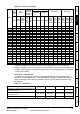
Maximum continuous output current (575V drives) FLC (A) Model FLC (A) 3501 3502 3503 3504 5.4 6.1 8.
11 1 41 42 Cons: Polar. signal 21 31 0V 1 +24V Input 2 Analog frequency / speed ref 1 0V com.