
User manual


IEC61131 User and Reference Manual
April 22, 2008
506
The Address Mapping contains a set of mapping rules, which will allow the Remote DNP Objects to
be mapped into local Modbus registers. This makes the data accessible locally, to be read and/or
written locally in logic. It is also possible to perform data concentration – to map the remote DNP
Objects into the local DNP address space – by defining local DNP objects and then mapping the
remote DNP objects to the same Modbus registers. Change events can also be mapped in the same
way - there is a configuration option to allow mapping of change events from a remote DNP slave
into the local DNP change event buffer. The table may have up to 1000 entries. A vertical scroll bar
is used if the list exceeds the window size.
The Station column displays the address of the remote DNP station.
The Object Type column displays the DNP data object type.
The First Point column displays the starting address of the remote DNP data points.
The Number column displays the number of remote points to be mapped.
The First Register column displays the starting address of local Modbus register where the remote
data points are to be mapped.
The Map Change Events combo box enables or disables mapping of change events from a remote
DNP slave into the local DNP change event buffer. Mapped change events may trigger an
Unsolicited message to be sent, after the Hold Count or Hold Time is reached. It may be desired
instead to map only static (live) values into local Modbus registers. The default selection is Disabled.
The default selection is Disabled.
The OK button saves the table data. No error checking is done on the table data.
The Cancel button closes the dialog without saving changes.
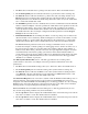
Select the Add button to enter a new row in the Address Mapping. Selecting the Add button opens
the Add/Edit Address Mapping dialog.