
Instruction Manual


3 - 60
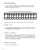
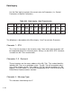
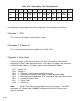
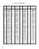
Table 3-32 Control Command Send - ML–Trim Response
Character # 1 2 3 4 5 6 7 8 9 10 11 12
DEV # DEV # ERROR PAR # PAR # DATA DATA DATA DATA DATA
DESC STX 10s 1s CODE 10s 1s 1000s 100s 10s 1s FORM ETX
ASCII STX 0-9 0-9 @-DEL 0 0 0 0 0-9 0-9 0 ETX
The following is a description of the Control Command Send-ML–Trim Response
Characters.
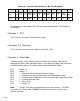
Character 1 - STX:
This is the first character in the character string.
Characters 2, 3 - Device #:
This is the two character access address for the ML–Trim.
Character 4 - Error Code:
If there are errors in the transmission that the ML–Trim receives from the host
computer, the Error Code will display them. Use Table 3-35 (page 3-66) to convert
the ASCII code to binary. The binary code can be decoded as follows:
Bit 7 Always “0”.
Bit 6 Always “1”.
Bit 5 1 = Data was out of minimum/maximum range.
Bit 4 1 = Checksum or Decimal Point Error, Invalid Parameter Code.
Bit 3 1 = Receive buffer filled before “ETX” received or Message Format Error.
Bit 2 1 = Invalid Parameter Data.
Bit 1 1 = Parity Error.
Bit 0 1 = Always “0”
Note: The ML–Trim will only accept data if there are no errors. The ASCII
error code “@” (Binary code “1000000”) indicates that the Host Transmission
contains no errors.