
Instruction Manual


vii
List of Illustrations
Figure 1-1 ML–Trim Master Mode ............................................................. 1-4
Figure 1-2 ML–Trim Follower Mode ........................................................... 1-5
Figure 2-1 ML–Trim Cutout Dimensions and Mounting Guide .................. 2-2
Figure 2-2 ML–Trim General Wiring Guide ............................................... 2-4
Figure 2-3 I/O Power (Isolated) .................................................................. 2-7
Figure 2-4 I/O Power (Non-Isolated) .......................................................... 2-7
Figure 2-5 AC Power .................................................................................. 2-8
Figure 2-6 Lead Frequency ....................................................................... 2-8
Figure 2-7 Feedback Frequency ............................................................... 2-9
Figure 2-8 Run ........................................................................................... 2-9
Figure 2-9 Jog .......................................................................................... 2-10
Figure 2-10 R–Stop .................................................................................... 2-10
Figure 2-11 F–Stop .................................................................................... 2-11
Figure 2-12 Master or Follower .................................................................. 2-11
Figure 2-13 Setpoint Select........................................................................ 2-12
Figure 2-14 Speed Command Out ............................................................. 2-13
Figure 2-15 Drive Enable and Alarms Outputs .......................................... 2-14
Figure 2-16 ML–Trim Multidrop Installation................................................ 2-15
Figure 2-17 ML–Trim Serial Communications Connections .................... 2-16
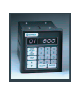
Figure 3-1 ML–Trim Front Panel ............................................................... 3-4
Figure 3-2 ML–Trim Internal Structure .................................................... 3-43
Figure 4-1 Motor Does Not Stop Flowchart ............................................ 4-12
Figure 4-2 Motor Does Not Run Flowchart ............................................. 4-13
Figure 4-3 Motor Runs at Wrong Speed Flowchart ................................ 4-14
Figure 4-4 Motor Runs Unstable Flowchart ............................................ 4-15
Figure 4-5 PROM Location ...................................................................... 4-17
Figure G-1 ML–Trim Wiring Connections without Relays ........................ G-1
Figure G-2 Relay Start/Stop Wiring Connections .................................... G-2
Figure G-3 Start/Stop for Regen with Armature Contactor ...................... G-3
Figure G-4 Start/Stop for Non-Regen with Armature Contactor .............. G-4
Figure G-5 Two Channel Start/Stop - Lead/Follower Logic ..................... G-5