
Instruction Manual

3 - 12
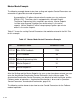
Master Mode Example
The following example demonstrates how scaling and setpoint Control Parameters are
entered for a typical Master mode of operation:
A pump delivers 15 gallons/minute when the motor runs at a maximum
RPM of 1725. The motor shaft is equipped with a 30 tooth Ring kit.
The Master Engineering Units are gallons per minute. Master Setpoint
1 will be setup to pump 10 gallons per minute when it is the active
setpoint. Master Setpoint 2 will be setup to pump 5 gallons per minute
when it is the active setpoint.
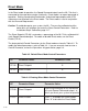
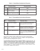
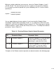
Table 3-7 shows the scaling Control Parameters that would be entered in the ML–Trim
for this example.
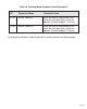
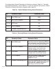
Table 3-7 Master Mode Control Parameters Example
CP Parameter Name Parameter Value
CP-34 Max RPM Feedback 1725
CP-31 PPR Feedback 30
CP-20 Master Engineering Units 15
CP-01 Master Setpoint 1 10
CP-02 Master Setpoint 2 5
After the Scaling and the Master Setpoints for your system have been entered, you can
enter the Acceleration/Deceleration Control Parameters for the Master mode. The
Acceleration/Deceleration Control Parameters are identical for both the Master and the
Follower modes of operations. Acceleration/Deceleration is discussed in
Operation:
Control Parameters, Acceleration/Deceleration,
page 3-26.
The following section demonstrates how to enter Control Parameters for the Follower
mode of operation.