
Manual

8900 Zachary Lane N., Maple Grove, MN 55369 U.S.A. 27
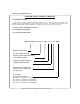
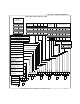
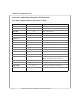
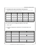
5.3 SINE/RESOLVER MODE AMPLIFIER CONFIGURATION:
The following table shows the dip switches that need to be configured for the Type A, B, C, and D
configurations. The standard configuration is shown in bold.
TYPE A TYPE B TYPE C TYPE D
LIMIT ±
S2-8 - OFF
S2-5 - ON
S2-8 - ON
S2-5 - OFF
S2-8 - OFF
S2-5 - OFF
S2-8 - ON
S2-5 - ON
INHIBIT
S2-7 - OFF
S2-4 - ON
S2-7 - ON
S2-4 - OFF
S2-7 - OFF
S2-4 - OFF
S2-7 - ON
S2-4 - ON
RESET IN S2-6 - OFF
S2-3 - ON
S2-6 - ON
S2-3 - OFF
S2-6 - OFF
S2-3 - OFF
S2-6 - ON
S2-3 - ON
MTR TEMP
S2-2 - ON not available
S2-2 - OFF
not available
FAULT
standard not available not available not available
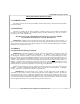
5.3.1 +15V/+5V Logic Level Configuration (DEFAULT:S2-1=OFF):
+15V: S2-1 = OFF.
+5V: S2-1 = ON.
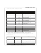
5.3.2 Standard Configuration for Sine/Resolver Velocity Mode and Current
Mode:
DIP-SWITCH NAME VELOCITY MODE CURRENT MODE
S1-1
ENCODER / 2 See section 5.3.3
S1-2
ENCDR * 125 / 128 See section 5.3.3
S1-3
(NOT USED) OFF OFF
S1-4
MTR REVERSE (normally OFF)
S1-5
TACH REVERSE (normally ON)
S1-6
INTEGRATOR
S1-7
VEL MODE ON OFF
S1-8
CUR MODE OFF ON
(normally OFF)
CHAPTER 5: CONFIGURATION