
Manual

8900 Zachary Lane N., Maple Grove, MN 55369 U.S.A. 11
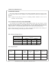
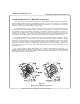
1.3.2 Mechanical
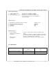
1.3.1.3 Digital Inputs:
+/-Limit, Inhibit & Reset: 40/-0.5V max. Terminated by 10,000S.
Fault (as input): 40/-0.5V max. Terminated by 10,000S.
Typical for all digital inputs: Digital inputs have hysteresis with thresholds
at 1/3 and and 2/3 of +5V or +15V depending on
range select jumper.
1.3.1.4 System:
Drift offset over temperature reference to input: 0.01mV/
o
C max.
Frequency response (Velocity loop): 750Hz min.
Frequency response (Current loop): 2KHz min.
Dead band: None.
Form factor: 1.01.
1.3.1.5 Outputs:
• Fault (as output): Active low. Open-collector output can sink 500mA max.
• Absolute motor current(J1-3): 10A/V.
• Tachometer : 1000S source impedance, a high input impedance meter must
be used (1M S /volt). Maximum Tachometer output voltage
for 12 bit = 1.5V/KRPM, 14 bit = 2V/KRPM.
• Encoder outputs: Standard TTL levels with 20mA sink or source capability.
(SMA8215)
CHAPTER 1: DESCRIPTION, FEATURES AND SPECIFICATIONS
Model L x W x H
(inches)
Weight
(lbs)
CXB1525 (Stand Alone Amplifier) 9.025 x 4.00 x 4.96 5.25
CXB2040 (Stand Alone Amplifier) 9.025 x 4.00 x 4.96 5.25