OPERATION & SERVICE MANUAL for CONTREX® Model CXB1525 Model CXB2040 Brushless Amplifier System MANUAL#: 0001-0200 REVISION: E DATE: 11-07-97 8900 Zachary Lane N., Maple Grove, MN 55369 U.S.A.
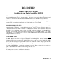
READ THIS! Model CXB1525/CXB2040 Brushless Servo Motor/Amplifier SETUP When a servo kit is purchased from CONTREX, the resolver has been aligned, and the motor/amplifier tuned for a 1:1 inertia match. The factory settings of the potentiometer's and switch's are recorded in the CXB1525/CXB2040 manual and on SK1650 for easy reference. The only potentiometer's that may need adjustment are the Loop Gain pot, which is shipped set at full CCW (off) and the Compensation pot, if the inertia is not a 1:1 match.
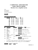
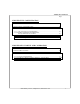
CALIBRATION - SETUP RECORD Model CXB1525/CXB2040 Brushless Servo Amplifier System Date: Model Number: Serial Number: Customer Order Number: ENCODER Resolution: DIP SWITCH CONFIGURATION Dip Switch S1 S2 1 ON / OFF ON / OFF 2 ON / OFF ON / OFF 3 ON / OFF ON / OFF 4 ON / OFF ON / OFF 5 ON / OFF ON / OFF 6 ON / OFF ON / OFF 7 ON / OFF ON / OFF 8 ON / OFF ON / OFF S3 ON / OFF ON / OFF ON / OFF ON / OFF ON / OFF ON / OFF ON / OFF ON / OFF POTENTIOMETER SETTING Pot Name of Pot Test Point Setting (Ohms) Notes RV2
TABLE OF CONTENTS Page INTRODUCTION ................................................................................................................ 6 CHAPTER ONE: DESCRIPTION, FEATURE AND SPECIFICATIONS 1.1 DESCRIPTION ............................................................................................................. 7 1.2 FEATURES ................................................................................................................... 7-9 1.2.1 Stand-alone Module ..................
CXB1525 and CXB2040 MANUAL Page CHAPTER THREE: MODEL NUMBERING 3.1 INTRODUCTION ......................................................................................................... 18 3.2 STAND ALONE AMPLIFIER....................................................................................... 18-19 3.2.1 Sine/Resolver Mode............................................................................................. 18-19 CHAPTER FOUR: INSTALLATION 4.1 INTRODUCTION ..................................
TABLE OF CONTENTS Page CHAPTER FIVE: CONFIGURATION 5.1 INTRODUCTION .......................................................................................................... 26 5.2 LOGIC INPUT CONFIGURATION .............................................................................. 26 5.3 SINE/RESOLVER MODE AMPLIFIER CONFIGURATION...................................... 27-29 5.3.1 +15V/+5V Logic Level Configuration ................................................................. 27 5.3.
CXB1525 and CXB2040 MANUAL Page 6.4 CALIBRATION-SETUP RECORD ............................................................................... 34 6.5 RESOLVER ALIGNMENT ........................................................................................... 35-36 CHAPTER SEVEN: MAINTANCE, REPAIR, AND WARRANTY 7.1 MAINTENANCE ........................................................................................................... 37 7.2 AMPLIFIER FAULTS ..................................................
TABLE OF CONTENTS Page APPENDIX A: AMPLIFIER DRAWINGS STAND-ALONE AMPLIFIER INSTALLATION DRAWING FOR SINE/RESOLVER MODE BRUSHLESS AMPLIFIER (8015-1036) ............................... 42 APPENDIX B: PERSONALITY MODULE SINE/RESOLVER MODE SCHEMATIC (8000-1430) ...................................................... 44-45 SINE/RESOLVER MODE ASSEMBLY (8000-1431) ........................................................ 46 8900 Zachary Lane N., Maple Grove, MN 55369 U.S.A.
CXB1525 and CXB2040 MANUAL INTRODUCTION CONTREX brushless motors and amplifiers offer the ultimate in low maintenance and high performance motion-control. CONTREX offers a full line of matched motors and amplifiers to meet virtually every motioncontrol application. This manual provides all the technical information necessary to install, configure, operate, and maintain our TORQUE-SWITCH™ series, brushless servo-motor amplifiers, models CXB1525 and CXB2040.
CHAPTER 1: DESCRIPTION, FEATURES AND SPECIFICATIONS CHAPTER ONE: DESCRIPTION, FEATURES AND SPECIFICATIONS 1.1 DESCRIPTION: This brushless amplifier system has been designed to offer you, our customer, a large degree of flexibility and customization with a standard, in stock product. Each amplifier module consists of a standard power output board with one of our three types of personality modules mounted on it.
CXB1525 and CXB2040 MANUAL • Surface mount technology: Constructed with surface mount components. • Complete isolation: Complete isolation from input to output. • Silent operation: Carrier frequency is 20KHz. • Short circuit protection: Complete short circuit and ground fault protection. • LED diagnostics: red LED(S) illuminate to display various fault conditions and a green LED illuminates to indicate normal operating conditions.
CHAPTER 1: DESCRIPTION, FEATURES AND SPECIFICATIONS • Manual and external fault reset: Push button and a separate input is provided to reset the amplifier after a fault. • High-Speed Electronic Circuit Breaker (HS/ECB): Instantly shuts down the amplifier in the event of a short across the outputs and or ground fault protection. (i.e.
CXB1525 and CXB2040 MANUAL 1.3 SPECIFICATIONS: This section contains the specifications for the brushless trapezoidal, sine/resolver and two or three phase input current mode D.C. Servo Amplifiers. These specifications also include power supplies for the amplifiers. o o NOTE: All data in this section is based on the following ambient conditions: 120 F (50 C) maximum. Forced air cooling. 1.3.
CHAPTER 1: DESCRIPTION, FEATURES AND SPECIFICATIONS 1.3.1.3 Digital Inputs: +/-Limit, Inhibit & Reset: Fault (as input): Typical for all digital inputs: 40/-0.5V max. Terminated by 10,000S. 40/-0.5V max. Terminated by 10,000S. Digital inputs have hysteresis with thresholds at 1/3 and and 2/3 of +5V or +15V depending on range select jumper. 1.3.1.
CXB1525 and CXB2040 MANUAL CHAPTER TWO: THEORY of OPERATION 2.1 INTRODUCTION: This chapter contains the basic control theory of how brush-type and brushless servo motors and amplifiers operate. It also compares and contrasts the advantages and disadvantages of brushless and brush-type motors and amplifiers to help you select which is best suited for your application. The following is a summary of the topics: The theory behind an amplifer driving DC servo-motors.
CHAPTER 2: THEORY OF OPERATION 2.3 SERVO LOOPS: A basic velocity-mode servo-loop for a brush-type motor is shown in figure 2.2a. An external controller commands a given velocity (RPM). The velocity-loop summing-amplifier compares this command with the actual motor velocity, supplied by a DC tachometer on the motor shaft, and produces an error voltage proportional to the difference between the actual and commanded velocity. The velocity error is used to command motor current in the inner servo-loop.
CXB1525 and CXB2040 MANUAL CHAPTER 2: THEORY OF OPERATION 2.4 BRUSHED MOTORS vs. BRUSHLESS MOTORS: There are two basic types of motor design that are used for high-performance motion control systems: brush-type PM (permanent magnet), and brushless-type PM. As you can see in figure 2.3, a brush-type motor has windings on the rotor (shaft) and magnets in the stator (frame). In a brushless-type motor, the magnets are on the rotor and the windings are in the stator.
CHAPTER 2: THEORY OF OPERATION BRUSHLESS MOTORS/AMPLIFIERS BRUSHED MOTORS/AMPLIFIERS ADVANTAGES DISADVANTAGES No scheduled maintenance and no brush dust is generated. Motor brushes must be checked periodically for wear and excess brush dust. Higher RPM limits. Approximately 3000RPM maximum. Lower inertia/torque ratio. Higher inertia to torque ratio. Dissipates heat more efficiently due to windings being located in stator. Not as efficient at dissipating heat.
CXB1525 and CXB2040 MANUAL 2.6 THE ADVANTAGES AND DISADVANTAGES OF A TRAPEZOIDAL AMPLIFIER SYSTEM: A trapezoidal motor has three stator windings and together with the rotor magnets are designed so that the magnetic flux coupling between them produce a constant torque. The torque of the motor is o proportional to the three stator phase currents which are 120 out-of-phase to the other two. Shaft position sensors are required to provide the commutation signals to commutate the motor.
CHAPTER 2: THEORY OF OPERATION 2.8 TACHOMETER (VELOCITY MODE) FEEDBACK OPTIONS: The following is a list of ways one can choose to implement tachometer feedback in order to drive the motor through a velocity controlled servo loop: Brush-type and brushless DC mechanical tachometer. Simulated tachometer using the motor commutation signals (PSEUDO-TACH). Sinusoidal resolver. Simulated tachometer using the encoder signals.
CXB1525 and CXB2040 MANUAL CHAPTER THREE: MODEL NUMBERING 3.1 INTRODUCTION: This chapter contains the model numbering system for the stand alone one axis amplifier and applications. The model numbering system is designed so that you, our customer will be able to create the correct model number of the product that you need as quick and as accurately as possible. 3.2 STAND ALONE AMPLIFIER MODULES: 3.2.1 SINE/RESOLVER MODE: 3.2.
CHAPTER 3: MODEL NUMBERING PRE-AMP CONFIGURATION CODE 4 BIT BINARY TO DIGIT CONVERSION 0000=0 0001=1 0010=2 0011=3 0100=4 0101=5 0110=6 0111=7 1000=8 1001=9 1010=A 1011=B 1100=C 1101=D 1110=E 1111=F Type A: U=0 & L=0 ( DEFAULT ) Type B: D=1 & H=1 Type C: U=0 & H=1 Type D: D=1 & L=0 See section 5.2 Number of Motor Poles 2 4 6 8 10 12 S3-1 S3-2 See section 5.3.4 1 1 1 1 1 1 1 1 1 0 1 0 S3-3 S3-4 1 1 0 0 1 1 1 0 1 0 1 0 PLD DEVICE CODE (See 5.3.
CXB1525 and CXB2040 MANUAL THIS PAGE LEFT BLANK INTENTIONALLY. 20 8900 Zachary Lane N., Maple Grove, MN 55369 U.S.A.
CHAPTER 4: INSTALLATION CHAPTER FOUR: INSTALLATION 4.1 INTRODUCTION: This chapter provides the necessary information to make all the wiring connections for the amplifiers to operate properly. 4.2 MOUNTING: Appendix A contains all the wiring diagrams, assembly drawings, and mechanical information necessary to install the amplifiers. The amplifier package should be mounted in a clean, dry enclosure, free of dust, oil, or other contaminants.
CXB1525 and CXB2040 MANUAL 4.3.2 Wire Size and Type: IMPORTANT: To ensure safe operation, CONTREX strongly recommends that all wiring conform to all local and national codes. RECOMMENDED WIRE SIZE and TYPE: MOTOR WIRES: 14AWG, shielded - STANDARD. 12AWG, shielded - HIGH POWER. MOTOR CASE GND: Same as motor wires, or use metallic conduit. MAIN POWER: Same as motor wires. SIGNAL INPUT: 22AWG, twisted-pair, shielded. LOGIC INPUTS/OUTPUTS: 22AWG, shielded with its return lead.
CHAPTER 4: INSTALLATION 4.3.3.2 The Signal Connector: The signal connectors are supported by the molex ® KK .100" (2,54mm) Centerline Connector System. A. J1 of MAIN AMP: ® MATING CONNECTOR: molex 2695 Series .100" (2,54mm) Center Crimp Terminal Housing (PART# 22-01-3175): - red nylon housing. - 15 positions. - with polarizing rib. ® CRIMP TERMINALS: molex Crimp Terminals (PART# 08-55-0102): - 15 microinch select gold plated. - brass. B.
CXB1525 and CXB2040 MANUAL 4.4 SINGLE AMPLIFIER MODULE CONNECTIONS: 4.4.1 Main Amplifier Module - Sine/Resolver Mode: SIGNAL NAME TERMINAL NOTES MOTOR R J2-3 Phase R of the motor. MOTOR S J2-2 Phase S of the motor. MOTOR T J2-1 Phase T of the motor. SIGNAL 1+ J1-1 Differential signal input. SIGNAL 1- J1-2 Differential signal return. SIGNAL 2+ J1-3 Single-ended signal 2 in. COMMON J1-4 Single-ended signal2 return. TACH OUT J1-5 DC output proportional to RPM.
CHAPTER 4: INSTALLATION 4.4.2 Pre-amp Module - Sine/Resolver Mode: SIGNAL NAME TERMINAL NOTES ENCODER (J4): A _ A J4-1 Phase A signal output. J4-2 Negative phase A signal output. B _ B J4-3 Phase B signal output. J4-4 Negative phase B signal output. Z _ Z J4-5 Phase Z signal output. J4-6 Negative phase Z signal output. COM RESOLVER (J5): J4-7 Common ground. SIN J5-1 Sine signal input. COM J5-2 Sine/Cosine return. COS J5-3 Cosine signal input. COM J5-4 Excitation return.
CXB1525 and CXB2040 MANUAL CHAPTER FIVE: CONFIGURATION 5.1 INTRODUCTION: Each amplifier has several configuration options. This chapter describes these options and how to implement them. If desired, CONTREX will be happy to pre-configure your amplifiers. NOTE: Each amplifier module is configured and shipped according to the model number (instructions to construct a model number is in chapter three) when the order is placed.
CHAPTER 5: CONFIGURATION 5.3 SINE/RESOLVER MODE AMPLIFIER CONFIGURATION: The following table shows the dip switches that need to be configured for the Type A, B, C, and D configurations. The standard configuration is shown in bold.
CXB1525 and CXB2040 MANUAL 5.3.3 Encoder Output Resolution Configuration: Refer to Appendix B drawing 8000-1430 and 8000-1431. There are nineteen standard resolutions. Up to four resolutions are contained in a single PLD. To configure the pre-amp for a given resolution, ensure that you have the correct PLD (U13) and then configure the dip-switches S1-1 and S1-2 as shown below. Resolution PLD CODE PLD PART NUMBER S1-1 S1-2 BITS MIN.
CHAPTER 5: CONFIGURATION 5.3.4 Motor Pole Configuration: Dip-switch S3-1, S3-2, S3-3 and S3-4 configures the pre-amp for the number of poles in the motor. They are also used to set up certain calibration modes. Refer to the chart below and set the dip switches for the correct number of poles.
CXB1525 and CXB2040 MANUAL CHAPTER SIX: START UP AND CALIBRATION 6.1 INTRODUCTION: This chapter contains the procedure required to calibrate and set up the amplifier. All adjustments are made on the pre-amp. Refer to Appendix B, drawing 8000-1430 & 8000-1431 for the sine/resolver mode. IF AMPLIFIER IS A REPLACEMENT OR ORDERED WITHIN A KIT, CALIBRATION IS USUALLY NOT NEEDED. Calibration requires an oscilloscope, a voltmeter, and a step-voltage source.
CHAPTER 6: START UP AND CALIBRATION 6.3 SINE/RESOLVER MODE AMPLIFIER CALIBRATION: 6.3.1 Overview of Potentiometer: POTS NAME OF POT NOTE RV2 SIG 1 (Signal 1) Sets the input voltage to RPM ratio, e.g. 10V=2000RPM (velocity mode) or input voltage to torque ratio, e.g. 10V=25A (current mode) required by your system for the single-ended input. RV3 SIG 2 (Signal 2) RV4 TACH (Tach Gain) RV5 BAL (Balance) Used to null any offsets in system.
CXB1525 and CXB2040 MANUAL The purpose of the following procedure is to set the system bandwidth to obtain a critically-damped response with the maximum possible tach gain. There are many possible settings of Tach Gain and Compensation which will yield a critically damped waveform. The optimum setting will occur when the Tach Gain is as CW as possible and the Compensation is as CCW as possible.
CHAPTER 6: START UP AND CALIBRATION 4. Connect the oscilloscope to ABS I (J1-7), and the battery box to the Signal 2 Single-ended Input (J13 and J1-4). The voltage on J1-7 is a function of motor current: 1V=10A. While pulsing a step input voltage, adjust the Current Limit for the desired peak current. If the desired peak current cannot be achieved with the pot full CW, increase the input voltage or increase the Signal 2 Gain (RV3). 5.
CXB1525 and CXB2040 MANUAL 6.4 CALIBRATION-SETUP RECORD: It is good practice to keep a record of all pot settings. Doing so will facilitate calibration on future units and repair on this unit. Although not a substitute for the calibration procedure, it will at least get you "in the ballpark." Remove the power and allow all capacitors to discharge before taking measurements. Note: The balance pot should not be measured in this fashion, set per step 4 in the calibration procedure.
CHAPTER 6: START UP AND CALIBRATION 6.5 RESOLVER ALIGNMENT: Note: CONTREX motors with built-in resolvers are factory aligned. Consult a CONTREX applications engineer prior to attempting a resolver realignment. Failure to do so may void the warranty. Note: Consult a CONTREX applications engineer before aligning a non-CONTREX motor/resolver. Some motor/resolvers require procedures other than that described here.
CXB1525 and CXB2040 MANUAL PROCEDURE: All adjustments are made to the 8000-14 Sine/Resolver pre-amp. Refer to Appendix 8000-1430 and 8000-1431. B, drawings 1. Connect and configure the amplifier as described in the installation section. Do not apply power yet. 2. Loosen the resolver mounting-screws just enough to allow the resolver to be adjusted. 3. Note the positions of S3-1, S3-2, S3-3 and S3-4, then set S3-1, S3-2, S3-3 and S3-4 for index (i.e. S31:ON, S3-2:OFF, S3-3:OFF and S3-4:OFF). 4.
CHAPTER 7: MAINTENANCE, REPAIR, and WARRANTY CHAPTER SEVEN: MAINTENANCE, REPAIR, and WARRANTY 7.1 MAINTENANCE: Contrex amplifiers do not require any scheduled maintenance, although it is a good idea to occasionally check for dust build-up or other contamination. 7.2 AMPLIFIER FAULTS: If an amplifier should cease to operate and one or more of the fault LED's are lit, review the sections which follow on the fault in question for information and possible causes.
CXB1525 and CXB2040 MANUAL 7.2.2 Under-Voltage Fault: When the +15VDC is below +12VDC, a level that would cause unreliable operation, the Run LED will turn off, a Fault Output is generated, and the amplifier is inhibited. This is not a latched condition: that is, if the problem is resolved the amplifier will resume operation. The following is a list of possible causes: 1. Main AC line voltage is too low. 2. Bad rectifier bridge. 3. Bad DC buss filter capacitor. 7.2.
CHAPTER 7: MAINTENANCE, REPAIR, and WARRANTY 7.2.6 Over Temp Fault: When the heatsink and or motor temperature has reached a level that, if exceeded, would damage the output transistors or the motor, the Run LED will turn off, the OVER TEMP LED is latched on, a Fault Output is generated, and the amplifier is inhibited. The following is a list of possible causes: 1. Loss of cooling air - Fans are defective or airflow is blocked. 2.
CXB1525 and CXB2040 MANUAL 7.4 FACTORY REPAIR: Should it become necessary to return an amplifier to CONTREX for repair, please follow the procedure described below: 1. Reassemble the unit, if necessary, making certain that all the hardware is in place. 2. Tag the unit with the following information: A. Serial number and model number. B. Company name, phone number, and representative returning the unit. C. A brief notation explaining the malfunction. D. Date the unit is being returned. 3.
APPENDIX A: AMPLIFIER DRAWINGS APPENDIX A AMPLIFIER DRAWINGS 8900 Zachary Lane N., Maple Grove, MN 55369 U.S.A.
CXB1525 and CXB2040 MANUAL 42 8900 Zachary Lane N., Maple Grove, MN 55369 U.S.A.
APPENDIX B PERSONALITY MODULE 8900 Zachary Lane N., Maple Grove, MN 55369 U.S.A.
CXB1525 and CXB2040 MANUAL 44 8900 Zachary Lane N., Maple Grove, MN 55369 U.S.A.
8900 Zachary Lane N., Maple Grove, MN 55369 U.S.A.
CXB1525 and CXB2040 MANUAL 46 8900 Zachary Lane N., Maple Grove, MN 55369 U.S.A.
NOTES 8900 Zachary Lane N., Maple Grove, MN 55369 U.S.A.
CXB1525 and CXB2040 MANUAL NOTES 48 8900 Zachary Lane N., Maple Grove, MN 55369 U.S.A.
High Bandwidth Brush Type Servo Amplifiers Linear Brush type servo amplifiers to 2.25KW PWM (Pulse-width-modulated) Brush type servo amplifiers to 70KW High Bandwidth Brushless Servo Amplifiers Linear Brushless servo amplifiers to 2.25KW PWM (Pulse-width-modulated) Brushless servo amplifiers to 65KW Permanent Magnet DC Brush Type Servo Motors Continuous Torques to 335 in. lb. Peak Torques to 2100 in. lb. Permanent Magnet DC Brushless Servo Motors Continuous Torques to 1100 in.