CX-1102 INSTALLATION/ WIRING GUIDE SK1691 Rev A
Installation / Wiring Guide Configuration Mounting Wiring Inputs Outputs Serial Communications DeviceNet (Optional) Logic Control Page 1
Page 2
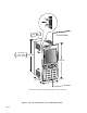
CONFIGURATION This section will show you how to re-configure the CX-1102 for electrical compatibility. Complete this procedure prior to installation. This procedure does not require power to complete. The area that is involved in re-configuring the CX-1102 is the AC Power Input Voltage switch. This switch is located in an external location on the CX-1102. You will not be required to access the interior of the CX-1102. Figure 1 (page 5) illustrates the location of this switch.
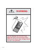
WARNING C ONT RE X me nu pag e pag e sta tus 7 8 4 par par cod set e help 9 5 1 6 2 Ñ 3 0 . cle ar ente r You will damage the CX-1102 if you apply 230 VAC to the AC Power input while the AC Power Input Voltage switch is in the 115 V position.
The AC Power Input Voltage switch is located on the rear of the CX-1102. The default configuration for the AC Power Input Voltage switch is 115 VAC. To re-configure for 230 VAC Input, move the switch from the 115V position (up) to the 230V position (down).
( XX XX XX XX XX XX XX CUTOUT " 3.65" .03 m 9.27± .07c 3.6" (9.1 cm) ( DOOR PANEL EX CONTR ( ) CUTOUT 7.25" ± .03" 18.41 ± .07 cm 7.2" (18.3 cm) 7.7" (19.6 cm) code menu help status 7 4 1 *6.3" (16.3 cm) - 8 5 2 0 9 6 3 . clear enter XX XX 4.0" m) (10.
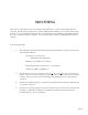
MOUNTING This section contains instructions for mounting the CX-1102 in the door panel of an industrial electrical enclosure. The CX-1102 is packaged in a compact 1/2 DIN vertical instrument enclosure that mounts easily in the door of your industrial electrical enclosure. The CX-1102 meets the NEMA 4 and the IP65 standards. To ensure compliance with these standards, enclose the CX-1102 in a Nema 4 or IP65 industrial electrical enclosure.
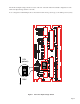
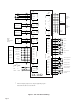
JA 2 Dncr 3 LnSpd 4 Com J5 1 SigU Drive Common 2 ComU Control Output To UWnd Drv Signal Input 2 ComW A A 3 A B 4 B B 5 B Com 6 Common A A 7 A 8 A B B 9 B 10 B Com 11 Reserved Drive Common SigW Control Output To Wnd Drv J8 1 +5V PWR 2 Wind Unwind Motor Drive Signal Input 1 A Encode Inputs J3 * +5VDC UnWind Line Speed +5VDC Analog Card Dancer 1 Unwind Quadrature Sensor Wind Quadrature Sensor Common RI_1 12 NC RI_2 13 NC +5V PWR Wind Moto
WIRING This section contains the input, output and serial communications wiring information for the CX-1102. Please read this section prior to wiring the CX-1102 to ensure that you make the appropriate wiring decisions. NOTE: The installation of this motor control must conform to area and local electrical codes. See The National Electrical Code (NEC,) Article 430 published by the National Fire Protection Association, or The Canadian Electrical Code (CEC).
INPUTS NOTE: The installation of this motor control must conform to area and local electrical codes. Refer to page 9 before you begin wiring. AC Power Input (J4 pins 1, 2,3) The CX-1102 operates on either a 115 VAC - 10% + 15%, 0.250 Amp., 50/60 Hz or a 230 VAC -10% +15%, 0.125 Amp, 50/60 Hz. Use the separate 3 pin connector (J4) for the power connection. * Fuse L1 for 115 VAC applications. Fuse L1 and L2 for 230 VAC applications. Use 1 Amp 250 normal blow fuses.
Unwind Frequency (J5 pins 1, 2, 4, 5, 6) The wiring for the Unwind Frequency is determined by the sensor. Figures 5 and 6 illustrate the wiring for the various sensors. For signal level and performance specifications, refer to Appendices: Appendix A . *+5V_Aux 1 +5V Pwr A 2 A A 3 A B 4 B B 5 B Com 6 Common Figure 5 Unwind Frequency Quadrature Differential Sensor (Bidirectional) J5 Total currant draw from the +5V_Aux (J5-Pin 1) should not exceed 150 Milliamps.
Wind Frequency (J5 pins 1, 7, 8, 9, 10, 11) The wiring for Wind Frequency is determined by the sensor. Figures 7 and 8 illustrate the wiring for the various sensors. For signal level and performance specifications refer to Appendices: Appendix A. *+5V_Aux 1 +5V Pwr A 7 A A 8 A B 9 B B 10 B Com 11 Common Figure 7 Wind Frequency Quadrature Differential Sensor (Bidirectional) J5 * Total currant draw from the +5V_Aux (J5-Pin 1) should not exceed 150 Milliamps.
F-Stop (J6 pins 1,3) F-STOP F-Stop is a momentary input. When it is opened, the CX-1102 commands a zero speed immediately and ignores the specified deceleration rate. However, F-Stop does not hold zero speed or position (drive disabled). As a momentary input, F-Stop is internally latched and does not need to be maintained open by an operator device.
Load (J6 pins 5, 3) LOAD When the Load input (J6, pin 5) is momentarily shorted to common, the CX-1102 enters the Load state. As a momentary input, Load is internally latched and does not need to be maintained closed by an operator device. Com 3 Load 5 J6 NOTE: Close the H-Stop, Unload and F-Stop inputs prior to entering the Load state. If you are only using one of the Stop inputs, wire short the other Stop inputs to the common or the CX-1102 will not enter load.
Keypad Lockout (J6 pins 9, 8) When the KEYPAD LOCKOUT input is closed, the Control Parameters that you have selected to "lockout" are inaccessible from the front keypad. All of the Monitor Parameters remain enabled. Com 8 KeyLk 9 ENABLE LOCKOUT J6 The Keypad Lockout input is temporally used during the system setup procedure to initiate tests for the CX1102 system setup procedure. Figure 15 Keypad Lockout Setup (J6 pins 10, 8) Setup is a maintained input.
Unwind Jog Reverse (J7 pins 2, 3) Unwind Jog Reverse is a maintained input. When it is closed, it sends a reverse unwind control output signal to the drive at the selected Jog Setpoint. As a maintained input, Unwind Jog Reverse is only active when the operator device is closed. NOTE: Close the H-Stop, Unload and F-Stop inputs prior to entering the Jog state. If you are only using one of the Stop inputs, wire short the other Stop inputs to the common or the CX-1102 will not enter Jog.
Unwind Under Wrap (J7 pins 6, 8) When the Unwind Under Wrap input is closed, then the unwind axle has web material fed off the roll from the bottom rather than the top of the roll. UNWIND UNDER WRAP UuWrp 6 Com 8 J7 Figure 21 Unwind Under Wrap Wind Under Wrap WIND UNDER WRAP (J7 pins 7, 8) When the Wind Under Wrap input is closed, then the wind axle has web material fed off the roll from the bottom rather than the top of the roll.
Web Reset (J7 pins 10, 8) WEB RESET Web Reset is a maintained input. When it is closed. As a maintained input, Web Reset is only active when the operator device is closed. Com 8 WbRst 10 J7 Figure 2-24 Web Reset Dancer (JA, Pins 1, 2, 4) The Dancer Input can be used with a potentiometer (e.g., dancer pot). +5V _Aux* 1 2 * The total current from JA pin 1 and J5 pin 1 (+5V_Aux) must not exceed 150 mA.
OUTPUTS NOTE: The installation of this motor control must conform to area and local electrical codes. Refer to page 9 before you begin wiring. Unwind Control Output (J8 pins 1, 2) Unwind Control Output is an isolated analog output signal that is sent to the motor drive to control the speed of the motor. Wire the Unwind Control Output into the speed signal input of the drive.
NOTE: All Digital Outputs are activated via the PLC and so are subject to the active PLC program. Unwind Enable (J2 pin 2) The Unwind Enable output is activated (driven low) when the CX-1102 signals a run command to the motor drive. The Unwind Enable output is driven high (relay deactivated) after Power Up and at the completion of F-Stop. See Figure 29. Wind Enable (J2 pin 3) The Wind Enable output is activated (driven low) when the CX-1102 signals a run command to the motor drive.
Web Break (J2 pin 8) The Web Break output is activated (driven low) when the dancer content is greater than or equal to 95% of DncrCtntFull (CP-272) and LineSpdRRef (MP-42) is greater than zero and the non-Dancer Trimmed Roll is rotaing at a speed greater than Zero Speed (CP-370). See Figure 29. Spare (J2 pin 9) The Spare output is activated (driven low) when the dancer content is within a band that is E5% of DncrCtntFull (CP-272) above or below the Dancer SP (CP-250). See Figure 29.
SERIAL COMMUNICATIONS NOTE: The installation of this motor control must conform to area and local electrical codes. Refer to page 9 before you begin wiring. The Serial Communications interface on the CX-1102 complies with EIA Standard RS-485-A for balanced line transmissions. This interface allows the host computer to perform remote computer parameter entry, status or performance monitoring, and remote control of the CX-1102. See Serial Communications for information on using Serial Communications.
RS232 to RS485 Converter TXD/ TXD/ COM RXD RXD - + J1 1 + TXD/RXD 2 - TXD/RXD 3 COM J1 2 CX-1102 #1 CX-1102 #2 1 + TXD/RXD 2 - TXD/RXD 3 COM 1 1. Shield only at one end of the cable. 2. If you need to terminate the communication line, then terminate it at the unit which is the furthest away from the converter. A 100 ohm, 1/2 Watt resistor will usually terminate successfully. Refer to EIA Standard RS–485A, for more information.
—NOTES— Page 24
DEVICENET CARD (OPTIONAL) For the installation, wiring and operation of the optional DeviceNet card, refer to the CX-Series DeviceNet Card Technical Manual, # 0001-0134.
—NOTES— Page 26
LOGIC CONTROL This section addresses the seven digital inputs that control the CX-1102's operating state. The seven digital inputs (listed by priority) are: F-Stop Unload H-Stop Run Load Jog Forward (Unwind and Wind) Jog Reverse (Unwind and Wind) When the CX-1102 is powered up, it defaults to F-Stop. Run is terminated by activating F-Stop, Unload or H-Stop. The operating state changes to the input that terminated Run, provided that another input is not subsequently activated.
Logic Inputs F-Stop (Fast Stop) has priority over the other operating states. F-Stop forces the Control Output SigU and SigW signals to “0” volts and monitors the feedback. When the feedback is less than the Zero Speed (CP370), the UwndDrvEn (PLC bit 41) and WindDrvEn (PLC bit 51) resets to “0”. This PLC bit is routed by the PLC program to an output that disables the drive.
Unload has the fourth highest operating priority. Only from Run, H-Stop, Load, or F-Stop states, but not from Direct Setpoint Application. Normal operation is from H-Stop with the dancer loaded. If Unload is requested from Run, the roll(s) ramp to zero speed before starting the Unload sequence below. Unload has a ten second (10s) timer. If the Dancer is not unloaded within 10 seconds after the Unload input is latched, the CX-1102 automatically reverts to the F-Stop operating state.
App Select (CP-202) = 1: The CX-1102 controls both rolls with Dancer Trimmed Unwind 1) The unwind is a bipolar or a unipolar reversible or a unipolar drive: a) The wind roll is put into H-Stop. b) The unwind roll jogs forward until the dancer is in the Full position. c) The unwind roll goes into Jog Stop until the unwind roll stops. d) Then the unwind roll transitions to F-Stop. e) The wind roll transitions to F-Stop. f) The system state transitions to F-Stop State.
App Select (CP-202) = 3: The CX-1102 controls only the Dancer Trimmed Unwind roll 1) The unwind is a bipolar or a unipolar reversible or a unipolar drive: a) The unwind roll jogs forward until the dancer is in the Full position. b) The unwind roll goes into Jog Stop until the unwind roll stops. c) Then the unwind roll transitions to F-Stop. d) The system state transitions to F-Stop State. 2) The unwind is a unipolar brake and the wind is bipolar or unipolar reversible: a) The unwind roll is put into H-Stop.
H-Stop (Stop and Hold) has the fifth highest operating priority. Use H-Stop to stop the drive with a deceleration ramp. The velocity command is ramped down to “0”. If the loop is “Closed”, the ramp is executed with velocity loop control (with feedforward, and Trim). If the loop is “Open”, the ramp will be executed with feedforward only. The deceleration rate for the ramp is determined by Dcl Tm HStp (CP-307) and Ref Ramps (CP-300) or by the Dcl Rt RStp (CP-308).
Run has the sixth highest operating priority. Run is the primary operating state. App Select (CP-202) determines the operation for Run, using either the applications 1 through 4 or the direct mode. The corresponding setpoint for the selected mode determines the operating speed. The direct mode will only operate as open loop. The applications 1 through 4 will “Run” in closed loop.
Load has the seventh highest operating priority. Only from F-Stop or Unload states. Normal operation is from F-Stop with the dancer in the full position. Load can also be initiated from Unload state with positive Dancer Error. Load has a ten second (10s) timer. If the Dancer is not loaded within 10 seconds after the Load input is latched the CX-1102 automatically reverts to the F-Stop operating state.
App Select (CP-202) = 1: The CX-1102 controls both rolls with Dancer Trimmed Unwind 1) If the unwind is a bipolar or a unipolar reversible drive: a) The wind roll is put into H-Stop. b) The unwind roll Jogs in reverse to pull material out of the dancer until the dancer error changes from positive to negative. c) The unwind roll goes into Jog Stop until the unwind roll stops. d) Then the unwind roll transitions to Run with Dancer Trim. e) The wind roll remains in H-Stop.
App Select (CP-202) = 4: The CX-1102 controls only the Dancer Trimmed Wind roll 1) If the wind is a bipolar or a unipolar reversible or a unipolar drive: a) The wind roll jogs forward to pull material out of the dancer until the dancer error changes from positive to negative. b) The wind roll goes into Jog Stop until the wind roll stops. c) Then the wind roll transitions to Run with Dancer Trim. d) The system state transitions to H-Stop State.
Jog Forward has the eighth highest operating priority. Use UJogF to “Jog” the unwind drive Forward or use WJogF to “Jog” the wind drive Forward at the rate indicated in Jog SP (CP-240). The acceleration and deceleration ramps are dictated by Acl Tm Jog (CP-241), Dcl Tm Jog (CP-243) and Jog SP (CP-240). After the UJogF or WJogF input is deactivated and the ramped reference has reached “0”, the CX-1102 automatically reverts to the F-Stop or H-Stop operating state.
Jog Reverse has nineth (the least) operating priority. Use UJogR to “Jog” the unwind drive Reverse or use WJogR to “Jog” the wind drive Reverse at the rate indicated in Jog SP (CP-240). The acceleration and deceleration ramps are dictated by Acl Tm Jog (CP-241), Dcl Tm Jog (CP-243) and Jog SP (CP-240). After the UJogR or WJogR input is deactivated and the ramped reference has reached “0”, the CX-1102 automatically reverts to the F-Stop or H-Stop operating state.
—NOTES— Page 39
CONTREX, INC. 8900 Zachary Lane North Maple Grove, MN 55369 USA Phone:763.424.7800 Fax: 763.424.8734 www.contrexinc.com info@contrexinc.