CX-1102 STARTUP GUIDE SK1676 Rev A
INTRODUCTION The CX-1102 motion controller is used with various types of motor drives for precision control of unwind/ wind applications. The typical application consists of a web or line coming off of a powered unwind roll, passing through a dancer loop and being taken up on a powered rewind roll. Both axis must have quadrature (bidirectional) encoders either on the motor shaft or on the roll shaft. Generally both of the axis will be under control of the CX-1102.
• Dancer Electrical Design: The analog electrical signal from the dancer should be stable, repeatable, noise-free, and linear with respect to dancer movement. It can be a potentiometer, or some non-contact analog sensor. Sonar or ultrasound detectors on a free loop web may not be acceptable due to instability or low resolution. The electrical signal does not necessarily have to traverse the entire 0 to 5 vdc range over the dancer range of physical motion.
—NOTES— Page 3
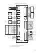
BASIC WIRING WARNING The CX-1102 should only be installed by a qualified electrician. Hazardous voltages may cause severe injury, death or equipment damage. The CX-1102 General Wiring Diagram illustrates the complete power and signal wiring for the CX-1102 control. Not all of the connections will be required for your application. Refer to the CX-1102 Technical Reference Manual for complete installation and wiring instructions.
CX-1102 General Wiring Diagram JA 2 Dncr 3 LnSpd 4 Com J5 1 SigU Drive Common 2 ComU Control Output To UWnd Drv Signal Input Drive Common 2 ComW A 2 A A 3 A B 4 B B 5 B Com 6 Common A A 7 A 8 A B B 9 B 10 B Com 11 Common RI_1 12 NC RI_2 13 NC Reserved SigW Control Output To Wnd Drv J8 1 +5V PWR Wind Unwind Motor Drive Signal Input 1 Encode Inputs J3 * +5VDC UnWind Line Speed +5VDC Analog Card Dancer 1 Unwind Quadrature Sensor Wind Quadratu
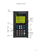
OPERATOR INTERFACE PRIMER The remainder of the CX-1102 setup procedure involves setting control parameter values through the operator interface, and then verifying system behavior using monitor parameters. The basic procedure for changing a control parameter is first to locate the relevant parameter using the Menu, Page Up/Down and Parameter Up/Down keys, and then to modify the parameter value using the Numeric or Scroll Up/Down keys.
CX-1102 Operator Interface LCD Screen Display CONTREX CX - 1102 MAIN MENU SETUP SCALING SETPOINTS & RAMPS TUNING ALARMS & LIMITS BLOCKS PLC SYSTEM MONITOR DEVICE TEST Menu Key Parameter Up/Down Keys (Par Up) (Par Dwn) Menu Alm Code Key Status Screen Key Page Up/Down Keys Numeric Keys MENU CODE STATUS HELP 7 8 9 4 5 6 1 2 3 - 0 .
SYSTEM SETUP PROCEDURE This procedure is a series of steps designed to verify the motor/drive/encoder wiring and polarity, calibrate the dancer and setup some of the basic parameters necessary for proper operation of the CX-1102. Before you begin this procedure, the motor and drive must be wired and configured in accordance with the manufacturer’s instructions.
DANGER Hazardous voltages. Can cause severe injury, death or damage the equipment. Make adjustments with caution.
Step 1 - Application Configuration - Parameter Entry Close the "Setup" input. The CX-1102 will change to "Setup State" and will automatically display System Setup Application\Page 1. Setup State {MP-59} will equal 0. Configure the CP’s on this screen as required.
Step 3 - Wind Roll Setup - Parameter Entry The CX-1102 will display System Setup Wind Roll\Page 3. Setup State {MP-59} will equal 2. Configure the CP’s on this screen as required.
Step 5 - Signal Polarity Test The CX-1102 will display System Setup Signal Polarity\Page 5. Setup State {MP-59} will equal 4. Setup State {MP-59} WindCO Volts {MP-37} WindCOPolarity {CP-287} WindEncRPM {MP-12} WindEncPty {CP-269} UwndCO Volts {MP-27} UwndCOPolarity {CP-282} UwndEncRPM {MP-02} UwndEncPty {CP-264} SigPolarity {MP-71} NOTE: The Help key accesses the Help screen and gives you a brief description of the parameter or subject that is highlighted (active) on the screen.
Fail test: The CX-1102 will flash "Wind Failure" then "Pg Up" in the bottom center of the display. Check the following: a. Control Output Unwind/Wind wiring to the drive b. encoder input wiring c. drive armature and power wiring d. is the drive enabled e. is this a Unipolar Reverse setup - check the PLC program and verify the correct connection to the drives reversing input. Press the "Page Up" key to restart this step (Wind Polarity Test).
The CX-1102 will change the UwndEncPty {CP-264} to match the control output signal based on the recorded information. For unipolar drives, UwndCOPolarity {CP-282} may also have been changed based on the recorded information. If the unwind axis is NOT under CX-1102 control or is Unipolar Brake: 1) Rotate the unwind roll in the forward direction, then in the reverse direction. 2) Observe the value in UwndEncRPM {MP-02} for a sign change. If the sign does not change then check the encoder input wiring.
Step 6 - Dancer Calibration The CX-1102 will display automatically System Setup Dancer\Page 6. Setup State {MP-59} will equal 6. Setup State {MP-59} DncrFullVolts {CP-271} DncrEmptyVlts {CP-273} DncrCtntFull {CP-272} Dancer SP {CP-250} DancerCtnt {MP-82} Dancer State {MP-58} Dancer Volts {MP-81} NOTE: The Help key accesses the Help screen and gives you a brief description of the parameter or subject that is highlighted (active) on the screen. Press the Help key again to return to the previous screen.
Step 7 - Wind Direction Test The CX-1102 will display automatically System Setup Wind Direction\Page 7. Setup State {MP-59} will equal 8. Setup State {MP-59} Wind State {MP-48} WindCO Volts {MP-37} WindRollRPM {MP-13} DancerCtnt {MP-82} WindCOPolarity {CP-282} WindEncPlrty {CP-264} Wrap Polarity {MP-70} Sig Polarity {MP-71} Wind Dirn {MP-61} NOTE: The Help key accesses the Help screen and gives you a brief description of the parameter or subject that is highlighted (active) on the screen.
If the dancer moves from Full to approximately 3/4 of Full, the Wind roll is stopped, the Dancer will be held in position, and the test Passes. Fail test: Check the following: a. is web threaded into machine b. drive armature and power wiring c. is the drive enabled d. gear reduction is correct Press the "Page Up" key to restart this step (Wind Direction Test). Pass test: The CX-1102 will flash "Wind PASS" then "Pg Down" in the bottom center of the display. Setup State {MP-59} will equal 9.
Step 8 - Unwind Direction Test The CX-1102 will display automatically System Setup Unwind Direction\Page 8. Setup State {MP-59} will equal 9. Setup State {MP-59} Uwnd State {MP-48} UwndCO Volts {MP-27} UwndRollRPM {MP-03} DancerCtnt {MP-82} UwndCOPolarity {CP-282} UwndEncPlrty {CP-264} Wrap Polarity {MP-70} Sig Polarity {MP-71} Uwnd Dirn {MP-60} NOTE: The Help key accesses the Help screen and gives you a brief description of the parameter or subject that is highlighted (active) on the screen.
If UwndCO Mode {CP-280} is set to Unipolar, this test Fails. If UwndCO Mode {CP-280} is set to Bipolar or Unipolar Reversing, UwndCOPolarity {CP-282} and UwndEncPlrty {CP-264} are changed, and a positive command is issued to the Unwind axis again for forward rotation (maximum of 2X number of rotations). The CX-1102 will montior the Dancer content for movement toward the Full position. If the Dancer moves to its Full position, both rolls are stopped, and the test Passes. Fail test: Check the following: a.
—NOTES— Page 20
—NOTES— Page 21
CONTREX, INC. 8900 Zachary Lane North Maple Grove, MN 55369 USA Phone:763.424.7800 Fax: 763.424.8734 www.contrexinc.com info@contrexinc.