
Owners Manual


16
BOTTLE, KEG & BACK BAR COOLERS, GLASS & PLATE CHILLERS
OPERATIONS MANUAL
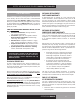
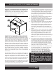
FIGURE 11: Sliding Glass Door Components
SPRING-LOADED
INTEGRAL HANDLE
MOUNTING FRAME
BACKBAR SLIDING GLASS DOOR ASSEMBLY
DOOR
(OUTER)
RIGHT HAND
DOOR
(INNER)
HANDLE
INTEGRAL
DOOR CLOSERS
DOOR SEAL
LEFT HAND
DOOR
SEAL
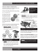
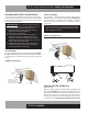
FIGURE 10: Electric Condensate Heater
IMPORTANT NOTE: It is extremely important to ensure
the condensate heater is plugged into the receptacle
labeled “vaporizer” and that the condensing unit is
plugged into the receptacle labeled “condensing unit.”
SLIDING GLASS DOOR REMOVAL AND ADJUSTMENT
All sliding glass doors are easily removable for thorough clean-
ing. To remove the doors, slide the outer door (see Figure
11) open about half way, grasp the door on both sides and
lift straight up, off the bottom of the mounting frame. Tilt the
bottom of the door out, so it clears the frame. Slide the door
towards its closed position, to release tension on the spring-
loaded door closer in the top of the mounting frame. Gently set
the door down in a safe location. Repeat this procedure for the
inner door.
To replace the doors, reverse the steps above, making sure the
pusher on the spring-loaded door closer seats properly against
the top of the door. If your sliding door does not close firmly,
remove the doors, starting with the outer door, as described
above. Check the bottom of the door, mounting frame channel,
and rollers to make sure they are clean and free of debris. If the
rollers are damaged or do not turn freely, contact the factory to
order replacement parts.
IMPORTANT NOTE: The glass used in sliding or hinged
glass doors is special, thermally sealed and cannot be
replaced with ordinary window or plate glass. Replacement
glass can be ordered directly from the factory.
2. All refrigerant should be removed from the system by a
qualified technician and disposed of properly, or reclaimed.
(Intentional venting of many refrigerants into the air is harm-
ful and prohibited; violators are subject to fines). All refriger-
ant oil should be drained from the compressor and discarded
appropriately.
3. Properly dispose of the cabinet and refrigeration system
components. The majority of the metal in your unit (stainless
steel or aluminum cabinet shell and doors, steel shelving and
compressor, copper refrigerant lines, etc.) can be recycled.
Many recycling facilities will dispose of the unit free of
charge, or pay you for scrap value of the material content
OPTIONAL ACCESSORIES
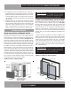
INSTALLING ELECTRIC CONDENSATE HEATER
The electric condensate heater has a power cord with a 15 amp
plug attached. To install the heater on a KC or BBC model, dis-
connect the power supply by unplugging the cabinet electrical
cord. Remove grill from the front of cabinet (see Figure 10) and
carefully set it aside. For easier access to the machine compart-
ments, the louvered end panel can also be removed. Place the
electric heater in the upper machine compartment as shown and
carefully position the end of the plastic drain tube into the heater
pan. Make sure tubing is not blocked or kinked and the end is
located securely, so any water running out of the tube will go
into the pan. Route the heater power cord through to the lower
machine compartment. Plug the cord into the receptacle labeled
“vaporizer” located on the wall between cabinet and the machine
compartment. Secure any excess power cord with a wire tie, so
it is away from hot or moving parts and does not fall into the
pan or under the cabinet. Reattach front grill and end panel. Plug
cabinet electrical cord into the power supply.