
Owners Manual


19
OPERATIONS MANUAL
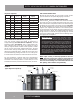
BOTTLE, KEG & BACK BAR COOLERS, GLASS & PLATE CHILLERS
1. All refrigerant lines and components must be clean, free of
burrs and purged with nitrogen prior to and during brazing
or soldering connections. Nitrogen purging during braz-
ing or soldering will eliminate carbon or foreign matter
contamination. Any system restrictions or contamination is
the responsibility of the installer.
2. Condensing unit or compressor shall not be left open to
the atmosphere for more than five (5) minutes.
3. No refrigeration component, tubing or fitting shall be left
open to the atmosphere for more than ½ hour without
being soldered, capped or plugged.
4. Each completed refrigeration system shall be purged with
150psi of dry nitrogen for at least six (6) seconds, then
pressurized with at least 165psi of nitrogen for pressure
check (making sure to energize any solenoid valves to
assure access). Leak-check all joints, flare fittings and
valves and make sure there is no pressure drop within the
system.
5. System evacuation is of the utmost importance with NON-
CFC refrigerant systems. System must be evacuated to a
minimum of 200 microns. In addition, a vacuum decay
test is strongly recommended to assure there is not a
large pressure differential between the system and the
vacuum pump. System must be evacuated from both high
and low sides of the system using heavy duty vacuum
hoses.
6. Each system should be charged with the refrigerant type
as specified on the cabinet data tag. This refrigerant type
should match the type listed on the condensing unit being
used. The refrigerant charge should be held to the mini-
mum required for the satisfactory pull down and opera-
tion. For an accurate indication of refrigerant charge, the
sight glass will show a full column of liquid.
7. The superheat reading taken 6” from the compressor suc-
tion valve should be 30° +/- 5°. Expansion valve adjust-
ment may be necessary to achieve this superheat.
8. Installation of the electric condensate heater is the
responsibility of the installer (see “Installing Electric
Condensate Heater” under “Optional Accessories”).
CAUTION: EXTREME CARE MUST BE USED WHEN
ACCESSING THE SYSTEM DURING INSTALLATION. DUE
TO THE COMPLEXITY OF REMOTE REFRIGERATION
SYSTEMS AND THE POTENTIAL FOR IMPROPER
INSTALLATION, ANY RESTRICTIONS, LEAKS, FAILED OR
DAMAGED COMPONENTS CAUSED BY CONTAMINANTS
ARE NOT THE RESPONSIBILITY OF CONTINENTAL
REFRIGERATOR.
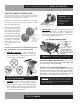
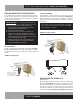
cabinet top, to avoid damaging wiring and refrigeration lines
in cabinet. Position keeper and attach to cabinet with (2) tam-
per-proof screws. Place lock plate through handle and keeper.
Secure with padlock (by others) through hole in plate.
REMOTE SET-UP AND INSTALLATION GUIDELINES
All remote refrigerators and freezers are shipped with an expan-
sion valve, thermostat and defrost timer (freezer only), installed
from the factory. The installer is responsible for connecting all
refrigerant lines, liquid line drier, sight glass, solenoid, head
pressure control, hi/low pressure safety, crankcase heater, con-
densing unit and any other accessories as well as wiring. The
evaporator section has been factory leak checked with helium,
however; due to vibration in transit, the entire system must be
thoroughly leak checked after installation and prior to start-up.
The final leak inspection of the entire completed refrigeration
system and all of its components as well as start-up and the
operation of the refrigeration system is the sole responsibility
of the installer.
The CFC-Free refrigerant used in standard remote and self-
contained models is R-134a for refrigerators and R-404a for
freezers. All compressors and systems designed for these
refrigerants utilize polyolester oil as their main lubricant, which
absorbs moisture from the ambient surroundings extremely fast
and in much greater quantity than conventional mineral oils.
Since moisture levels greater than 100 PPM will result in system
corrosion and ultimate failure, it is imperative that the compres-
sor, components and entire system be kept sealed.
FIGURE 16: Padlock Installation
11/02/10