
Install Manual
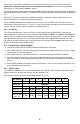
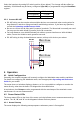
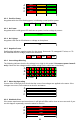
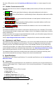
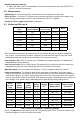
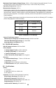
Table Of Contents

12
For other LED patterns, see the Operating and Reference Guide or contact support for assis-
tance.
4.3 Modbus Communication LED
Near the upper left corner, there is a diagnostic Com (communication) LED that can indicate the
following:
●
Green
Off
A short green flash indicates a valid packet addressed to this device.
●
Yellow
Off
Short yellow flashes or rapid flashing indicate valid packets addressed to differ-
ent devices.
●
Red
A one second red flash indicates an invalid packet: bad baud rate, bad
CRC, noise, bad parity, etc.
●
YR YR YR
Rapid red/yellow flashing indicates a possible address conflict (two
devices with the same DIP switch address).
●
Red
Solid red indicates the address is set to zero: an invalid choice.
4.4 Monitoring
The WattNode Modbus meter models communicate measurements over a Modbus RTU network.
The measurements include: energy, power, voltage, current, line frequency, power factor, reactive
power, and demand.
In order to monitor and configure networked WattNode models, you will need an appropriate moni-
toring solution, either standalone or PC software.
See the Operating and Reference Guide for a complete list of network accessible variables.
4.5 Maintenance and Repair
The WattNode meter requires no maintenance. It is not user serviceable and there are no replace-
able parts except the pluggable screw terminals. There are no diagnostic tests that can be per-
formed by the user, other than checking for errors via the Modbus interface or the status LEDs.
In the event of any failure, the meter must be returned for service (contact CCS for an RMA). For
a new installation, follow the troubleshooting instructions in the Operating and Reference Guide
before returning the meter for service, to ensure that the problem is not connection related.
The WattNode meter should not normally need to be cleaned, but if cleaning is desired, power
must be disconnected first and a dry or damp cloth or brush should be used.
5 Specifications
The following is a list of basic specifications. For extended specifications, see the Operating and
Reference Guide.
5.1 Accuracy
The following accuracy specifications do not include errors caused by the current transformer ac-
curacy or phase angle errors. “Rated current” is the current that generates a CT output voltage of
0.33333 Vac.
Normal Operation:
● Line voltage: -20% to +15% of nominal
● Power factor: 1.0
● Frequency: 48 - 62 Hz
● Ambient Temperature: 23°C ± 5°C
● CT Current: 5% - 100% of rated current
Accuracy: ±0.5% of reading
For accuracy at other conditions, see the reference guide.