
Install Manual
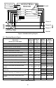
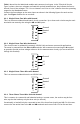
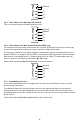
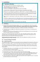
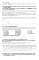
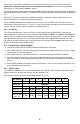
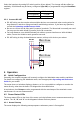
Table Of Contents

10
Select the baud rate by setting DIP switch position 8 (see below). The change will take effect im-
mediately. 38,400 baud may be factory configured (Opt 38K) or programmed using the BaudRate
register.
Baud Rate DIP Switch 8
9,600 (default) 0, Down
19,200 1, Up
3.5.2 Connect RS-485
● RS-485 wiring can be complex when multiple devices are connected, when running wires for
long distances, and when using termination and biasing resistors. If you have any questions,
consult the Operating and Reference Guide.
● Be sure to connect the A-, B+, and C (common) terminals. The X terminal is normally not used.
You may use the cable shield (if present) for the C connection.
● For long distances, use shielded twisted-pair cable to prevent interference. With shielded
cable, connect the shield to earth ground at one end.
● RS-485 wiring is daisy-chained between meters, with up to 64 devices per subnet.
X
C
B
+
A
-
W
ATT
N
ODE
WATTNODE
A
-
B
+
C
RS
-
485
X
C
B
+
A
-
4 Operation
4.1 Initial Configuration
Generally, the network integrator will remotely configure the WattNode meter and the variables.
For details on configuring the WattNode meter, see the appropriate Operating and Reference
Guide for your model.
The meter does not include a display or buttons, so it is not possible to configure or monitor the
meter directly, other than the basic LED diagnostics described below.
At a minimum, the CtAmps must be programmed with the rated amps of the attached current
transformers for correct measurements.
4.2 Power Status LEDs
The three status LEDs on the front of the meter can help indicate correct measurements and op-
eration. The “A”, “B”, and “C” on the diagrams indicate the three phases.
4.2.1 Normal Startup
The meter displays the following startup sequence whenever power is first applied.