WattNode Modbus and WattNode Revenue ® ® ® Electric Power Meter - Installation Manual WattNode Modbus Models WattNode Revenue for Modbus Models WNC-3Y-208-MB WNC-3Y-400-MB WNC-3Y-480-MB WNC-3Y-600-MB WNC-3D-240-MB WNC-3D-400-MB WNC-3D-480-MB RWNC-3Y-208-MB RWNC-3Y-400-MB RWNC-3Y-480-MB RWNC-3Y-600-MB RWNC-3D-240-MB RWNC-3D-400-MB RWNC-3D-480-MB Continental Control Systems LLC www.ccontrolsys.
Contents 1 1.9 Precautions...............................................................................................................................3 Symbols......................................................................................................................................3 2 2.1 2.2 Overview....................................................................................................................................3 Additional Literature......................................
1 Precautions 1.1 Only qualified personnel or licensed electricians should install the WattNode meter. The mains voltages of 120 to 600 Vac can be lethal! 1.2 Follow all applicable local and national electrical and safety codes. 1.3 The terminal block screws are not insulated. Do not contact metal tools to the screw terminals if the circuit is live! 1.4 Verify that circuit voltages and currents are within the proper range for the meter model. 1.
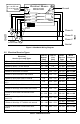
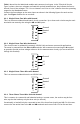
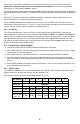
A−, D0, RxD−/TxD− B+, D1, RxD+/TxD+ Common Continental Control Systems LLC A- B+ C WHITE BLACK WHITE BLACK X WHITE BLACK WATTNODE MODBUS ® MODBUS EIA-485 Monitoring Device Com Ground WNC- 3Y-xxx-MB WNC-3D-xxx-MB N ØA CT Status ØA ØB CT Status ØB ØC CT Status ØC Source Faces Phase A Phase C Current Transformers LINE LOAD Phase B Neutral Figure 1: WattNode Wiring Diagram 2.2 Electrical Service Types 1 Phase 2 Wire 120V with neutral 1 Phase 2 Wire 230V with neutral (non-U.S.
Table 1 above lists the WattNode models and common circuit types. In the “Electrical Service Types” column, when two voltages are listed with a slash between them, they indicate the line-toneutral / line-to-line voltages. The “Line-to-Neutral” and “Line-to-Line” columns show the operating ranges for the WattNode meters. Connect the line voltages to the meter inputs as shown in the following figures for each service type. See Figure 1 above for an overview. 2.2.
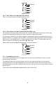
WATTNODE ® Ground N ØA L1 ØB L2 ØC L3 2.2.5 Three-Phase Four-Wire Wye with Neutral This is a common commercial and industrial service. WATTNODE ® ØA Ground Neutral L1 ØB L2 ØC L3 N 2.2.6 Three-Phase Four-Wire Delta with Neutral (Wild Leg) The uncommon four-wire delta electrical service is a three-phase delta service with a center-tap on one of the transformer windings to create a neutral for single-phase loads.
3 Installation 3.1 Installation Checklist See the sections referenced below for installation details. □□ Turn off power before making line voltage connections. □□ Mount the WattNode meter (see 3.2). □□ Connect circuit breakers or fuses and disconnects (see 3.3.1). □□ Connect the line voltage wires to the meter’s green terminal block (see 3.3.2). □□ Mount the CTs around the line conductors. Make sure the CTs face the source (see 3.4).
3.3.2 Line Wiring ● Always turn off power before connecting the line voltage inputs to the meter. ● For the line voltage wires, CCS recommends 16 to 12 AWG stranded wire, type THHN, MTW, or THWN, 600 V. ●● Do not place more than one voltage wire in a screw terminal; use separate wire nuts or terminal blocks if needed. ● Verify that the line voltages match the line-to-line Ø-Ø and line-to-neutral Ø-N values printed in the white box on the front label.
Install the CTs around the conductor to be measured and connect the CT leads to the meter. Always turn off power before disconnecting any live conductors. Put the line conductors through the CTs as shown in Figure 1 above. CTs are directional. If they are mounted backwards or with their white and black wires swapped the measured power will be negative. The status LEDs indicate negative measured power by flashing red. Split-core CTs can be opened for installation around a conductor.
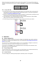
Select the baud rate by setting DIP switch position 8 (see below). The change will take effect immediately. 38,400 baud may be factory configured (Opt 38K) or programmed using the BaudRate register. Baud Rate 9,600 (default) 19,200 DIP Switch 8 0, Down 1, Up 3.5.2 Connect RS-485 ●● RS-485 wiring can be complex when multiple devices are connected, when running wires for long distances, and when using termination and biasing resistors. If you have any questions, consult the Operating and Reference Guide.
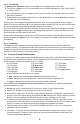
A B C Red Yellow Green Red Yellow Green Red Yellow Green 1.0sec 1.0sec 1.0sec 4.2.2 Positive Power Any phase with the LEDs flashing green is indicating normal positive power. Green Off Off Green Green Off 4.2.3 No Power Any phase with a solid green LED indicates no power, but line voltage is present. Green 4.2.4 No Voltage Any phase LED that is off indicates no voltage on that phase. Off 4.2.5 Negative Power Red flashing indicates negative power for that phase.
For other LED patterns, see the Operating and Reference Guide or contact support for assistance. 4.3 Modbus Communication LED Near the upper left corner, there is a diagnostic Com (communication) LED that can indicate the following: ●● Green Off A short green flash indicates a valid packet addressed to this device. ●● Yellow Off ent devices.
WattNode Revenue Models: ●● Meets the ANSI C12.1-2008 standard for revenue metering when used with IEEE C57.13 class 0.6 current transformers. 5.2 Measurement Update Rate: 1.0 second. Internally, all measurements are performed at this rate. Start-Up Time: ~1.0 second. The meter starts communicating this long after AC voltage is applied. Energy measurement starts 50-100 milliseconds after AC is applied. Default CT Phase Angle Correction: 0.0 degrees. 5.
Maximum Power Supply Voltage Range: -20% to +15% of nominal (see table above). For the 3D-240 service, this is -20% of 208 Vac (166 Vac) to +15% of 240 Vac (276 Vac). Operating Frequencies: 50/60 Hz Measurement Category: CAT III Measurement category III is for measurements performed in the building installation.
Voltage Dips, Interrupts: EN 61000-4-11 Emissions: ●● FCC Part 15, Class B ●● EN 55022: 1994, Class B Revenue Metering: ●● ANSI C12.1-2008 5.6 Environmental Operating Temperature: -30°C to +55°C (-22°F to 131°F) Altitude: Up to 2000 m (6560 ft) Operating Humidity: non-condensing, 5 to 90% relative humidity (RH) up to 40°C, decreasing linearly to 50% RH at 55°C.
5.9 Warranty All products sold by Continental Control Systems, LLC (CCS) are guaranteed against defects in material and workmanship for a period of five years from the original date of shipment. CCS’s responsibility is limited to repair, replacement, or refund, any of which may be selected by CCS at its sole discretion. CCS reserves the right to substitute functionally equivalent new or serviceable used parts.