
Install Manual

Wiring
● For the line voltage wires, CCS recommends 16
to 12 AWG stranded wire, type MTW, THWN, or
THHN, 600 V.
● Do not place more than one voltage wire in a
screw terminal; use separate wire nuts or termi-
nal blocks if needed.
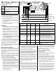
● Verify that the line voltages match the line-to-line
Ø-Ø and line-to-neutral Ø-N values printed in the
white box on the front label.
● The meter is powered from the line voltage in-
puts: ØA (phase A) to N (neutral), or ØA to ØB
for delta models.
Always disconnect power before connecting
the line voltage inputs to the meter. Connect each
line voltage to the appropriate phase; also connect
ground and neutral (if applicable). The neutral con-
nection “N“ is not required on models starting with
WNC-3D, but we recommend connecting it to ground
if neutral is not present.
The screw terminals handle wire up to 12 AWG. Pre-
pare the voltage wires by stripping the wires to ex-
pose 1/4" (6 mm) of bare wire. Connect each voltage
line to the green terminal block as shown in Figure 1
above. Verify that the line voltage phases match the
CT phases. After the voltage lines have been con-
nected, make sure both terminal blocks are securely
installed on the meter.
When power is first applied, check that the LEDs
behave normally: if you see the LEDs flashing red-
green-red-green (see Figure 7 below), then discon-
nect the power immediately! This indicates the line
voltage is too high for this model.
Connect Modbus (RS-485) Outputs
● RS-485 wiring can be complex when multiple
devices are connected, when running wires for
long distances, and when using termination and
biasing resistors. If you have any questions, con-
sult the full “Installation and Operation Manual”.
● The outputs are isolated from dangerous volt-
ages, so you can connect them at any time.
● If the output wiring is near line voltage wiring,
use wires or cables with a 300 V or 600 V rating.
● If the cable is near bare conductors, like bus-
bars, it should be double insulated or jacketed.
● Be sure to connect the A-, B+, and C terminals.
The X terminal is normally not used. You may
use the cable shield for the C connection.
● For long distances, use shielded twisted-pair ca-
ble to prevent interference. With shielded cable,
connect the shield to earth ground at one end.
The WattNode Modbus meter can be connected to
PCs with RS-485 interfaces and to data loggers or
other devices that accept RS-485 Modbus devices.
Configure DIP Switches
Use DIP switches 1-7 to select the Modbus address
(1 to 127) and switch 8 to select the baud rate (OFF
= 9600, ON = 19200).
Installation Summary
1) Mount the WattNode meter.
2) Turn off power before installing toroidal CTs or
making voltage connections.
3) Mount the CTs around the line conductors. Take
care to orient the CTs facing the source.
4) Connect the twisted white and black wires from
the CT to the black terminal block on the meter,
matching the wire colors to the white and black
dots on the meter label.
5) Install or connect appropriate circuit breakers or
fuses and disconnects.
6) Connect the line voltage wires to the green
terminal block of the meter, and check that the
CT phases match the line voltage phases.
7) Connect the output terminals of the WattNode
meter to the monitoring equipment.
8) Check that all the wires are securely installed in
the terminal blocks by tugging on each wire.
9) Apply power to the meter.
10) Verify that the LEDs light correctly and don’t in-
dicate an error condition.
Register Configuration
For a full list of registers and settings, see the “In-
stallation and Operation Manual”. At a minimum, the
CtAmps register must be programmed with the rated
amps of the attached current transformers.
Modbus Com Diagnostic LED
Near the upper left corner, there is a Modbus diag-
nostic LED that can indicate the following:
●
Green
A short green flash indicates a good
packet addressed to this device.
●
Yellow
A short yellow flash indicates a good
packet addressed to a different device.
●
Red
A one second red flash indi-
cates an invalid packet: bad baud rate, bad par-
ity, bad CRC, noise, etc.
●
Red
Solid red indicates the
address is set to zero: an invalid choice.
●
YR YR YR
Rapid red/yellow flashing
indicates a possible Modbus address conflict.
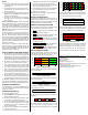
Power Diagnostic LEDs
The three status LEDs on the front of the meter can
help indicate correct operation. The “A”, “B”, and “C”
on the diagrams indicate the three phases.
1.0sec
1.0sec1.0sec
GreenYellowRed
GreenYellowRed
GreenYellowRed
C
B
A
Figure 2: Normal Startup
The meter displays this startup sequence whenever
power is first applied.
Green
Off
Green
Off
Green
Off
Figure 3: Positive Power
Any phase with the LEDs flashing green is indicating
normal positive power.
Green
Figure 4: No Power
Any phase with a solid green LED indicates no power,
but line voltage is present.
Off
Figure 5: No Power - Zero Vac
Any phase LED that is off indicates no voltage on
that phase.
Red
Off
Red
Off
Red
Off
C
Figure 6: Negative Power
Red flashing indicates negative power for that
phase. Reversed CTs, swapped CT wires, or CTs
not matched with line voltage phases can cause this.
1.0sec
GR GR GR GR GR GR
GR GR GR GR
GR GR
GR GR GR GR
GR GR
C
B
A
Figure 7: LED Overvoltage Warning
The line voltage is too high for this model. Disconnect
power immediately! Check the line voltages and the
meter ratings (in the white box on the label).
Off
Off
Off
C
B
A
Figure 8: Meter Not Operating
If none of the LEDs light, then check that the correct
line voltages are applied to the meter. If the voltages
are correct, call customer service for assistance.
3.0sec
Red
Red
Red
C
B
A
Figure 9: WattNode Error
If the meter experiences an internal error, it will light
all LEDs red for three or more seconds. If you see
this happen repeatedly, return the meter for service.
For other LED patterns, see the “Installation and
Operation Manual” or contact support for assistance.
©2009-2011 Continental Control Systems, LLC.
3131 Indian Rd.
Boulder, CO 80301
(303) 444-7422
http://www.ccontrolsys.com
WattNode is a registered trademark of Continental
Control Systems, LLC.
Document Number: WNC-MB-QIG-V18b
Revision Date: Nov. 30, 2011